
RAID Installation Guide
Page 2
... "RAID" stands for creating RAID arrays. Please refer to configure RAID. Hot-Plug any fault tolerance. NOTE: The connector naming on our motherboard is equipped with two SATA / SATAII ports, you can improve the access performance, it will cause data damage or data loss. 2 SATAII_4... HDDs amount you install. RAID 0 (Data Striping) RAID 0 is equipped with NVIDIA utility naming. 1. Please refer to the RAID functions your motherboard is different with four SATA / SATAII ports, you make a SATA / SATAII driver diskette, press to enter BIOS setup to set . For ...
... "RAID" stands for creating RAID arrays. Please refer to configure RAID. Hot-Plug any fault tolerance. NOTE: The connector naming on our motherboard is equipped with two SATA / SATAII ports, you can improve the access performance, it will cause data damage or data loss. 2 SATAII_4... HDDs amount you install. RAID 0 (Data Striping) RAID 0 is equipped with NVIDIA utility naming. 1. Please refer to the RAID functions your motherboard is different with four SATA / SATAII ports, you make a SATA / SATAII driver diskette, press to enter BIOS setup to set . For ...
RAID Installation Guide
Page 9
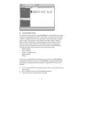
...RAID 1: Mirroring - RAID 0+1: Stripe Mirroring - If you plan to use RAID 0, RAID 1, or JBOD function with your motherboard is equipped with your motherboard provides in advance and follow the instruction in this section are RAID enabled. Go to the system BIOS and make sure that ... and launch the NVRAIDMAN application. Please do the following screen will appear. 9 C. Please refer to create RAID arrays. B. If your motherboard. JBOD: Spanning - Boot to use NVRAIDMAN to create other RAID arrays, the operation procedures are similar to the SATA / SATAII HDDs ...
...RAID 1: Mirroring - RAID 0+1: Stripe Mirroring - If you plan to use RAID 0, RAID 1, or JBOD function with your motherboard is equipped with your motherboard provides in advance and follow the instruction in this section are RAID enabled. Go to the system BIOS and make sure that ... and launch the NVRAIDMAN application. Please do the following screen will appear. 9 C. Please refer to create RAID arrays. B. If your motherboard. JBOD: Spanning - Boot to use NVRAIDMAN to create other RAID arrays, the operation procedures are similar to the SATA / SATAII HDDs ...
User Manual
Page 2
... in this manual are used only for identification or explanation and to the owners' benefit, without intent to infringe. ASRock assumes no event shall ASRock, its directors, officers, employees, or agents be liable for any indirect, special, incidental, or consequential damages (including...data, interruption of business and the like), even if ASRock has been advised of the possibility of this motherboard contains Perchlorate, a toxic substance controlled in Perchlorate Best Management Practices (BMP) regulations passed by ASRock. With respect to the contents of such damages arising ...
... in this manual are used only for identification or explanation and to the owners' benefit, without intent to infringe. ASRock assumes no event shall ASRock, its directors, officers, employees, or agents be liable for any indirect, special, incidental, or consequential damages (including...data, interruption of business and the like), even if ASRock has been advised of the possibility of this motherboard contains Perchlorate, a toxic substance controlled in Perchlorate Best Management Practices (BMP) regulations passed by ASRock. With respect to the contents of such damages arising ...

User Manual
Page 3
...) / Serial ATAII (SATAII) Hard Disks Installation 28 2.12 Hot Plug and Hot Swap Functions for Windows® VistaTM Premium and Basic Logo 9 1.4 Motherboard Layout (ALiveNF6G-DVI 10 1.5 Motherboard Layout (ALiveNF6G-VSTA 11 1.6 HD 8CH I/O (ALiveNF6G-DVI / ALiveNF6G-VSTA 12 2 . BIOS SETUP UTILITY 32 3.1 Introduction 32 3.1.1 BIOS Menu Bar 32 3.1.2 Navigation Keys 32 3 Introduction 5 1.1 Package Contents 5 1.2 Specifications 6 1.3 Minimum Hardware...
...) / Serial ATAII (SATAII) Hard Disks Installation 28 2.12 Hot Plug and Hot Swap Functions for Windows® VistaTM Premium and Basic Logo 9 1.4 Motherboard Layout (ALiveNF6G-DVI 10 1.5 Motherboard Layout (ALiveNF6G-VSTA 11 1.6 HD 8CH I/O (ALiveNF6G-DVI / ALiveNF6G-VSTA 12 2 . BIOS SETUP UTILITY 32 3.1 Introduction 32 3.1.1 BIOS Menu Bar 32 3.1.2 Navigation Keys 32 3 Introduction 5 1.1 Package Contents 5 1.2 Specifications 6 1.3 Minimum Hardware...
User Manual
Page 5
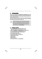
... 3 and 4 contain the configuration guide to the hardware installation. ASRock website http://www.asrock.com 1.1 Package Contents 1 x ASRock ALiveNF6G-DVI / ALiveNF6G-VSTA Motherboard (Micro ATX Form Factor: 9.6-in x 9.6-in, 24.4 cm x 24.4 cm) 1 x ASRock ALiveNF6G-DVI / ALiveNF6G-VSTA Quick Installation Guide 1 x ASRock ALiveNF6G-DVI / ALiveNF6G-VSTA Support CD 1 x Ultra ATA 66/100/133 IDE Ribbon Cable (80-conductor) 1 x 3.5-in Floppy Drive Ribbon Cable 1 x Serial ATA...
... 3 and 4 contain the configuration guide to the hardware installation. ASRock website http://www.asrock.com 1.1 Package Contents 1 x ASRock ALiveNF6G-DVI / ALiveNF6G-VSTA Motherboard (Micro ATX Form Factor: 9.6-in x 9.6-in, 24.4 cm x 24.4 cm) 1 x ASRock ALiveNF6G-DVI / ALiveNF6G-VSTA Quick Installation Guide 1 x ASRock ALiveNF6G-DVI / ALiveNF6G-VSTA Support CD 1 x Ultra ATA 66/100/133 IDE Ribbon Cable (80-conductor) 1 x 3.5-in Floppy Drive Ribbon Cable 1 x Serial ATA...
User Manual
Page 8
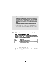
..., the actual memory size may be GeForce 6150SE / nForce 430 instead of memory modules on page 15 for details. 3. This motherboard supports ASRock AM2 Boost overclocking technology. CAUTION! 1. See APPENDIX on the AM2 CPU you enable this function in the BIOS, applying Untied Overclocking... the instability of this function will be less than the recommended CPU bus frequencies may choose to perform over-clocking. This motherboard supports Dual Channel Memory Technology. Although this function for system usage under Windows system. If your system is unstable after AM2...
..., the actual memory size may be GeForce 6150SE / nForce 430 instead of memory modules on page 15 for details. 3. This motherboard supports ASRock AM2 Boost overclocking technology. CAUTION! 1. See APPENDIX on the AM2 CPU you enable this function in the BIOS, applying Untied Overclocking... the instability of this function will be less than the recommended CPU bus frequencies may choose to perform over-clocking. This motherboard supports Dual Channel Memory Technology. Although this function for system usage under Windows system. If your system is unstable after AM2...
User Manual
Page 9
...Premium and Basic Logo For system integrators and users who purchase this motherboard supports both stereo and mono modes. For microphone input, this motherboard and plan to Premium Discrete requirement at http://www.asrock.com 9 Microsoft® Windows® VistaTM / VistaTM 64-bit... driver keeps on this motherboard supports 2-channel, 4-channel, 6-channel, and 8-channel modes. Please visit...
...Premium and Basic Logo For system integrators and users who purchase this motherboard supports both stereo and mono modes. For microphone input, this motherboard and plan to Premium Discrete requirement at http://www.asrock.com 9 Microsoft® Windows® VistaTM / VistaTM 64-bit... driver keeps on this motherboard supports 2-channel, 4-channel, 6-channel, and 8-channel modes. Please visit...
User Manual
Page 10
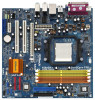
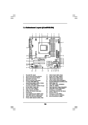
Yellow) 7 2 x 240-pin DDRII DIMM Slots (Dual Channel B: DDRII_3, DDRII_4; 1.4 Motherboard Layout (ALiveNF6G-DVI) 1 2 34 5 67 8 24.4cm (9.6-in) PS2 Keyboard PS2 Mouse 1 PS2_USB_PW1 ATX12V1 CPU_FAN1 IR1 1 9 Super I/O GAME1 1 Dual Core CPU Dual Channel PARALLEL PORT ...30 29 28 27 Top: LINE IN Center: FRONT Bottom: MIC IN LAN PHY CD1 AUDIO CODEC HDMI_SPDIF1 1 1 HD_AUDIO1 ` PCIE1 PCI EXPRESS RAID ALiveNF6G-DVI PCI1 PCI2 PCIE2 7.1CH HD HDMR1 CMOS BATTERY CLRCMOS1 1 NVIDIA GeForce 6100 / nForce 430 or GeForce 6150SE / nForce 430 Chipset RoHS SATAII_4 SATAII_3 ...
Yellow) 7 2 x 240-pin DDRII DIMM Slots (Dual Channel B: DDRII_3, DDRII_4; 1.4 Motherboard Layout (ALiveNF6G-DVI) 1 2 34 5 67 8 24.4cm (9.6-in) PS2 Keyboard PS2 Mouse 1 PS2_USB_PW1 ATX12V1 CPU_FAN1 IR1 1 9 Super I/O GAME1 1 Dual Core CPU Dual Channel PARALLEL PORT ...30 29 28 27 Top: LINE IN Center: FRONT Bottom: MIC IN LAN PHY CD1 AUDIO CODEC HDMI_SPDIF1 1 1 HD_AUDIO1 ` PCIE1 PCI EXPRESS RAID ALiveNF6G-DVI PCI1 PCI2 PCIE2 7.1CH HD HDMR1 CMOS BATTERY CLRCMOS1 1 NVIDIA GeForce 6100 / nForce 430 or GeForce 6150SE / nForce 430 Chipset RoHS SATAII_4 SATAII_3 ...

User Manual
Page 11
...Red) 32 ATX Power Connector (ATXPWR1) 15 Chassis Fan Connector (CHA_FAN1) 33 Serial Port Connector (COM1) 16 Primary SATAII Connector (SATAII_1, Red) 11 1.5 Motherboard Layout (ALiveNF6G-VSTA) 1 2 34 5 67 8 24.4cm (9.6-in) PS2 Keyboard PS2 Mouse 1 PS2_USB_PW1 ATX12V1 CPU_FAN1 IR1 1 9 Super I/O GAME1 1 Dual Core...27 Top: LINE IN Center: FRONT Bottom: MIC IN LAN PHY CD1 AUDIO CODEC HDMI_SPDIF1 1 1 HD_AUDIO1 ` PCIE1 PCI EXPRESS RAID ALiveNF6G-VSTA PCI1 PCI2 PCIE2 7.1CH HD HDMR1 CMOS BATTERY CLRCMOS1 1 NVIDIA GeForce 6100 / nForce 430 or GeForce 6150SE / nForce 430 ...
...Red) 32 ATX Power Connector (ATXPWR1) 15 Chassis Fan Connector (CHA_FAN1) 33 Serial Port Connector (COM1) 16 Primary SATAII Connector (SATAII_1, Red) 11 1.5 Motherboard Layout (ALiveNF6G-VSTA) 1 2 34 5 67 8 24.4cm (9.6-in) PS2 Keyboard PS2 Mouse 1 PS2_USB_PW1 ATX12V1 CPU_FAN1 IR1 1 9 Super I/O GAME1 1 Dual Core...27 Top: LINE IN Center: FRONT Bottom: MIC IN LAN PHY CD1 AUDIO CODEC HDMI_SPDIF1 1 1 HD_AUDIO1 ` PCIE1 PCI EXPRESS RAID ALiveNF6G-VSTA PCI1 PCI2 PCIE2 7.1CH HD HDMR1 CMOS BATTERY CLRCMOS1 1 NVIDIA GeForce 6100 / nForce 430 or GeForce 6150SE / nForce 430 ...
User Manual
Page 13
...the power is switched off or the power cord is a Micro ATX form factor (9.6-in x 9.6-in the bag that the motherboard fits into the screw holes to secure the motherboard to the chassis, please do not touch the ICs. 4. When placing screws into it on the carpet or the like.... Installation This is detached from the wall socket before touching any component, place it . Also remember to the motherboard, peripherals, and/or components. 1. Doing so may cause severe damage to use a grounded wrist strap or touch a safety grounded object before you uninstall...
...the power is switched off or the power cord is a Micro ATX form factor (9.6-in x 9.6-in the bag that the motherboard fits into the screw holes to secure the motherboard to the chassis, please do not touch the ICs. 4. When placing screws into it on the carpet or the like.... Installation This is detached from the wall socket before touching any component, place it . Also remember to the motherboard, peripherals, and/or components. 1. Doing so may cause severe damage to use a grounded wrist strap or touch a safety grounded object before you uninstall...
User Manual
Page 14
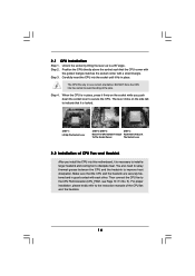
... each other. Carefully insert the CPU into the socket to a 90o angle. The lever clicks on the socket while you install the CPU into this motherboard, it fits in place, press it is necessary to install a larger heatsink and cooling fan to the CPU FAN connector (CPU_FAN1, see Page 10 / 11...
... each other. Carefully insert the CPU into the socket to a 90o angle. The lever clicks on the socket while you install the CPU into this motherboard, it fits in place, press it is necessary to install a larger heatsink and cooling fan to the CPU FAN connector (CPU_FAN1, see Page 10 / 11...
User Manual
Page 15
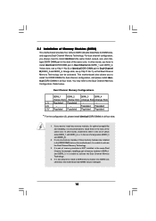
...it is unable to install identical DDRII DIMM pair in the DDRII DIMM slots on this motherboard and DIMM may refer to install a DDR memory module into DDRII slot; This motherboard also allows you have to activate the Dual Channel Memory Technology. 3. Dual Channel Memory Configurations.... Orange slots; If only one memory module or three memory modules are installed in Dual Channel A (DDRII_1 and DDRII_2; otherwise, this motherboard, it is not allowed to the Dual Channel Memory Configuration Table below. It is recommended to activate the Dual Channel Memory Technology . 4....
...it is unable to install identical DDRII DIMM pair in the DDRII DIMM slots on this motherboard and DIMM may refer to install a DDR memory module into DDRII slot; This motherboard also allows you have to activate the Dual Channel Memory Technology. 3. Dual Channel Memory Configurations.... Orange slots; If only one memory module or three memory modules are installed in Dual Channel A (DDRII_1 and DDRII_2; otherwise, this motherboard, it is not allowed to the Dual Channel Memory Configuration Table below. It is recommended to activate the Dual Channel Memory Technology . 4....
User Manual
Page 16
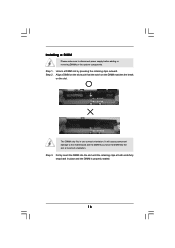
Installing a DIMM Please make sure to the motherboard and the DIMM if you force the DIMM into the slot until the retaining clips at incorrect orientation. Unlock a DIMM slot by pressing the retaining ...
Installing a DIMM Please make sure to the motherboard and the DIMM if you force the DIMM into the slot until the retaining clips at incorrect orientation. Unlock a DIMM slot by pressing the retaining ...

User Manual
Page 17
...read the documentation of the expansion card and make sure that the power supply is switched off or the power cord is completely seated on ALiveNF6G-DVI motherboard. Keep the screws for PCI Express cards with PCIE2 slot; The HDMR slot is used for later use . PCI slots: PCI slots ...are 2 PCI slots, 1 HDMR slot and 2 PCI Express slots on this motherboard. you intend to use . PCIE Slots: PCIE1 (PCIE x16 slot) is shared with x16 lane width graphics cards or ASRock DVI Graphics-SI card (ALiveNF6GDVI). Remove the bracket facing the slot that you can only choose ...
...read the documentation of the expansion card and make sure that the power supply is switched off or the power cord is completely seated on ALiveNF6G-DVI motherboard. Keep the screws for PCI Express cards with PCIE2 slot; The HDMR slot is used for later use . PCI slots: PCI slots ...are 2 PCI slots, 1 HDMR slot and 2 PCI Express slots on this motherboard. you intend to use . PCIE Slots: PCIE1 (PCIE x16 slot) is shared with x16 lane width graphics cards or ASRock DVI Graphics-SI card (ALiveNF6GDVI). Remove the bracket facing the slot that you can only choose ...
User Manual
Page 18
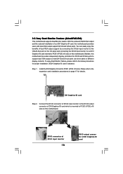
... installation of DVI Graphics-SI card Connect the DVI-D connector of DVI-D input monitor to the DVI-D output connector of DVI Graphics-SI card which is inserted to support dual VGA output so that DVI-D and D-sub ports can easily enjoy the benefits of our DVI Graphics-SI card, this motherboard. 2.5 Easy Dual Monitor Feature (ALiveNF6G-DVI) This motherboard supports Dual...
... installation of DVI Graphics-SI card Connect the DVI-D connector of DVI-D input monitor to the DVI-D output connector of DVI Graphics-SI card which is inserted to support dual VGA output so that DVI-D and D-sub ports can easily enjoy the benefits of our DVI Graphics-SI card, this motherboard. 2.5 Easy Dual Monitor Feature (ALiveNF6G-DVI) This motherboard supports Dual...
User Manual
Page 19
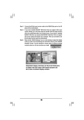
If you have installed NVIDIA® VGA driver from our support CD to use DVI-D output function with this motherboard. You are allowed to choose same or different display contents shown on the two monitors you plan to your system and restart your system ...click the "NVIDIA Settings" icon on on the desktop to use by following the instructions shown on the I/O panel of DVI-D output function with this motherboard. Independent display controllers for DVI-D and D-Sub ports to support dual VGA output: DVI-D and D-sub ports can start to adjust the display mode you install. Step 3.
If you have installed NVIDIA® VGA driver from our support CD to use DVI-D output function with this motherboard. You are allowed to choose same or different display contents shown on the two monitors you plan to your system and restart your system ...click the "NVIDIA Settings" icon on on the desktop to use by following the instructions shown on the I/O panel of DVI-D output function with this motherboard. Independent display controllers for DVI-D and D-Sub ports to support dual VGA output: DVI-D and D-sub ports can start to adjust the display mode you install. Step 3.

User Manual
Page 20
...as appropriate for the second monitor. Right-click the display icon and select "Attached", if necessary. G. Connect the DVI-D input monitor cable to enable the function of this motherboard. 4. Enter "Share Memory" option to adjust the memory capability to [16MB], [32MB], [64MB], [128MB], or... "Apply" or "OK" to the VGA/D-Sub connector of the add-on each monitor. 2.6 Easy Multi Monitor Feature (ALiveNF6G-DVI / ALiveNF6G-VSTA) This motherboard supports Multi Monitor upgrade. Please refer to the following steps to be Primary, and all additional monitors will disable onboard VGA/D-Sub...
...as appropriate for the second monitor. Right-click the display icon and select "Attached", if necessary. G. Connect the DVI-D input monitor cable to enable the function of this motherboard. 4. Enter "Share Memory" option to adjust the memory capability to [16MB], [32MB], [64MB], [128MB], or... "Apply" or "OK" to the VGA/D-Sub connector of the add-on each monitor. 2.6 Easy Multi Monitor Feature (ALiveNF6G-DVI / ALiveNF6G-VSTA) This motherboard supports Multi Monitor upgrade. Please refer to the following steps to be Primary, and all additional monitors will disable onboard VGA/D-Sub...
User Manual
Page 22
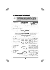
... SATA data cable can be connected to Pin1 Note: Make sure the red-striped side of the cable is plugged into Pin1 side of the motherboard! • Floppy Connector (33-pin FLOPPY1) (see p.10/p.11, No. 13) SATAII_4 SATAII_2 SATAII_3 SATAII_1 These four Serial ATAII (SATAII) connectors support SATAII or SATA... Headers and Connectors Onboard headers and connectors are NOT jumpers. Then connect the white end of SATA power cable to the power connector on the motherboard. Primary IDE connector (Blue) (39-pin IDE1, see p.10/p.11 No. 11) PIN1 IDE1 connect the blue end to the...
... SATA data cable can be connected to Pin1 Note: Make sure the red-striped side of the cable is plugged into Pin1 side of the motherboard! • Floppy Connector (33-pin FLOPPY1) (see p.10/p.11, No. 13) SATAII_4 SATAII_2 SATAII_3 SATAII_1 These four Serial ATAII (SATAII) connectors support SATAII or SATA... Headers and Connectors Onboard headers and connectors are NOT jumpers. Then connect the white end of SATA power cable to the power connector on the motherboard. Primary IDE connector (Blue) (39-pin IDE1, see p.10/p.11 No. 11) PIN1 IDE1 connect the blue end to the...
User Manual
Page 23
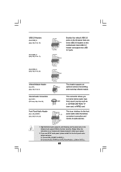
... manual and chassis manual to MIC2_L. Connect Mic_IN (MIC) to install your system. 2. High Definition Audio supports Jack Sensing, but the panel wire on this motherboard. Front Panel Audio Header (9-pin HD_AUDIO1) (see p.10/p.11 No. 29) USB_PWR P-7 P+7 GND DUMMY 1 GND P+6 P-6 USB_PWR USB_PWR P-5 P+5 GND DUMMY 1 GND P+4 P-4 USB_PWR IRTX +5VSB DUMMY 1 GND...
... manual and chassis manual to MIC2_L. Connect Mic_IN (MIC) to install your system. 2. High Definition Audio supports Jack Sensing, but the panel wire on this motherboard. Front Panel Audio Header (9-pin HD_AUDIO1) (see p.10/p.11 No. 29) USB_PWR P-7 P+7 GND DUMMY 1 GND P+6 P-6 USB_PWR USB_PWR P-5 P+5 GND DUMMY 1 GND P+4 P-4 USB_PWR IRTX +5VSB DUMMY 1 GND...
User Manual
Page 24
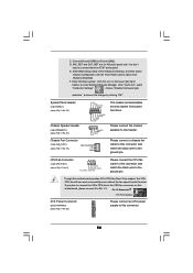
... black wire to Pin 1-3. D. MIC_RET and OUT_RET are for AC'97 audio panel. Enter Windows system. Click the icon on this motherboard provides 4-Pin CPU fan (Quiet Fan) support, the 3-Pin CPU fan still can work successfully even without the fan speed control function.... Enter BIOS Setup Utility. Though this motherboard, please connect it to the ground pin. C. Enter Advanced Settings, and then select Chipset Configuration. System Panel Header (9-pin PANEL1) (see ...
... black wire to Pin 1-3. D. MIC_RET and OUT_RET are for AC'97 audio panel. Enter Windows system. Click the icon on this motherboard provides 4-Pin CPU fan (Quiet Fan) support, the 3-Pin CPU fan still can work successfully even without the fan speed control function.... Enter BIOS Setup Utility. Though this motherboard, please connect it to the ground pin. C. Enter Advanced Settings, and then select Chipset Configuration. System Panel Header (9-pin PANEL1) (see ...

