User Manual
Page 5
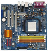
... and endurance. You may find the latest VGA cards and CPU support lists on ASRock website without notice. ASRock website http://www.asrock.com 1.1 Package Contents 1 x ASRock ALiveNF6G-DVI / ALiveNF6G-VSTA Motherboard (Micro ATX Form Factor: 9.6-in x 9.6-in, 24.4 cm x 24.4 cm) 1 x ASRock ALiveNF6G-DVI / ALiveNF6G-VSTA Quick Installation Guide 1 x ASRock ALiveNF6G-DVI / ALiveNF6G-VSTA Support CD 1 x Ultra ATA 66/100/133 IDE Ribbon Cable (80-conductor) 1 x 3.5-in Floppy...
... and endurance. You may find the latest VGA cards and CPU support lists on ASRock website without notice. ASRock website http://www.asrock.com 1.1 Package Contents 1 x ASRock ALiveNF6G-DVI / ALiveNF6G-VSTA Motherboard (Micro ATX Form Factor: 9.6-in x 9.6-in, 24.4 cm x 24.4 cm) 1 x ASRock ALiveNF6G-DVI / ALiveNF6G-VSTA Quick Installation Guide 1 x ASRock ALiveNF6G-DVI / ALiveNF6G-VSTA Support CD 1 x Ultra ATA 66/100/133 IDE Ribbon Cable (80-conductor) 1 x 3.5-in Floppy...
Quick Installation Guide
Page 1
... business, loss of data, interruption of business and the like), even if ASRock has been advised of the possibility of ASRock Inc. CALIFORNIA, USA ONLY The Lithium battery adopted on this motherboard contains Perchlorate, a toxic substance controlled in this guide. Disclaimer: Specifications and ...subject to the following two conditions: (1) this device may apply, see www.dtsc.ca.gov/hazardouswaste/perchlorate" ASRock Website: http://www.asrock.com Published February 2007 Copyright©2007 ASRock INC. All rights reserved. 1 ASRock ALiveNF6G-DVI / ALiveNF6G-VSTA Motherboard English
... business, loss of data, interruption of business and the like), even if ASRock has been advised of the possibility of ASRock Inc. CALIFORNIA, USA ONLY The Lithium battery adopted on this motherboard contains Perchlorate, a toxic substance controlled in this guide. Disclaimer: Specifications and ...subject to the following two conditions: (1) this device may apply, see www.dtsc.ca.gov/hazardouswaste/perchlorate" ASRock Website: http://www.asrock.com Published February 2007 Copyright©2007 ASRock INC. All rights reserved. 1 ASRock ALiveNF6G-DVI / ALiveNF6G-VSTA Motherboard English

Quick Installation Guide
Page 2
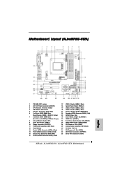
... Internal Audio Connector: CD1 (Black) 30 PCI Slots (PCI1- 2) 31 PCI Express x16 Slot (PCIE1) 32 ATX Power Connector (ATXPWR1) 33 Serial Port Connector (COM1) 2 ASRock ALiveNF6G-DVI / ALiveNF6G-VSTA Motherboard Motherboard Layout (ALiveNF6G-DVI) English 1 PS2_USB_PW1 Jumper 2 ATX 12V Power Connector (ATX12V1) 3 CPU Heatsink Retention Module 4 AM2 940-Pin CPU Socket 5 CPU Fan Connector (CPU_FAN1) 6 2 x 240-pin DDRII...
... Internal Audio Connector: CD1 (Black) 30 PCI Slots (PCI1- 2) 31 PCI Express x16 Slot (PCIE1) 32 ATX Power Connector (ATXPWR1) 33 Serial Port Connector (COM1) 2 ASRock ALiveNF6G-DVI / ALiveNF6G-VSTA Motherboard Motherboard Layout (ALiveNF6G-DVI) English 1 PS2_USB_PW1 Jumper 2 ATX 12V Power Connector (ATX12V1) 3 CPU Heatsink Retention Module 4 AM2 940-Pin CPU Socket 5 CPU Fan Connector (CPU_FAN1) 6 2 x 240-pin DDRII...
Quick Installation Guide
Page 3
...) 30 PCI Slots (PCI1- 2) 31 PCI Express x16 Slot (PCIE1) 32 ATX Power Connector (ATXPWR1) 33 Serial Port Connector (COM1) 3 ASRock ALiveNF6G-DVI / ALiveNF6G-VSTA Motherboard Yellow) 7 2 x 240-pin DDRII DIMM Slots (Dual Channel B: DDRII_3, DDRII_4; Motherboard Layout (ALiveNF6G-VSTA) English 1 PS2_USB_PW1 Jumper 2 ATX 12V Power Connector (ATX12V1) 3 CPU Heatsink Retention Module 4 AM2 940-Pin CPU Socket 5 CPU Fan...
...) 30 PCI Slots (PCI1- 2) 31 PCI Express x16 Slot (PCIE1) 32 ATX Power Connector (ATXPWR1) 33 Serial Port Connector (COM1) 3 ASRock ALiveNF6G-DVI / ALiveNF6G-VSTA Motherboard Yellow) 7 2 x 240-pin DDRII DIMM Slots (Dual Channel B: DDRII_3, DDRII_4; Motherboard Layout (ALiveNF6G-VSTA) English 1 PS2_USB_PW1 Jumper 2 ATX 12V Power Connector (ATX12V1) 3 CPU Heatsink Retention Module 4 AM2 940-Pin CPU Socket 5 CPU Fan...

Quick Installation Guide
Page 4
... 2.0 Ports (USB01) 10 USB 2.0 Ports (USB23) 11 VGA Port 12 PS/2 Keyboard Port (Purple) 13 PS/2 Mouse Port (Green) * If you use front panel audio. 4 ASRock ALiveNF6G-DVI / ALiveNF6G-VSTA Motherboard English TABLE for connection details in accordance with the type of speaker you are allowed to select "Realtek HDA Primary output" to use Rear Speaker...
... 2.0 Ports (USB01) 10 USB 2.0 Ports (USB23) 11 VGA Port 12 PS/2 Keyboard Port (Purple) 13 PS/2 Mouse Port (Green) * If you use front panel audio. 4 ASRock ALiveNF6G-DVI / ALiveNF6G-VSTA Motherboard English TABLE for connection details in accordance with the type of speaker you are allowed to select "Realtek HDA Primary output" to use Rear Speaker...
Quick Installation Guide
Page 5
... robust design conforming to ASRock's commitment to change without further notice. ASRock website http://www.asrock.com 1.1 Package Contents 1 x ASRock ALiveNF6G-DVI / ALiveNF6G-VSTA Motherboard (Micro ATX Form Factor: 9.6-in x 9.6-in, 24.4 cm x 24.4 cm) 1 x ASRock ALiveNF6G-DVI / ALiveNF6G-VSTA Quick Installation Guide 1 x ASRock ALiveNF6G-DVI / ALiveNF6G-VSTA Support CD 1 x Ultra ATA 66/100/133 IDE Ribbon Cable (80-conductor) 1 x 3.5-in the Support CD. Introduction Thank you for ALiveNF6G-DVI) 5 ASRock ALiveNF6G-DVI / ALiveNF6G-VSTA Motherboard English
... robust design conforming to ASRock's commitment to change without further notice. ASRock website http://www.asrock.com 1.1 Package Contents 1 x ASRock ALiveNF6G-DVI / ALiveNF6G-VSTA Motherboard (Micro ATX Form Factor: 9.6-in x 9.6-in, 24.4 cm x 24.4 cm) 1 x ASRock ALiveNF6G-DVI / ALiveNF6G-VSTA Quick Installation Guide 1 x ASRock ALiveNF6G-DVI / ALiveNF6G-VSTA Support CD 1 x Ultra ATA 66/100/133 IDE Ribbon Cable (80-conductor) 1 x 3.5-in the Support CD. Introduction Thank you for ALiveNF6G-DVI) 5 ASRock ALiveNF6G-DVI / ALiveNF6G-VSTA Motherboard English
Quick Installation Guide
Page 6
... Platform - Supports Wake-On-LAN Rear Panel I/O HD 8CH I/O - 1 x PS/2 Mouse Port - 1 x PS/2 Keyboard Port 6 ASRock ALiveNF6G-DVI / ALiveNF6G-VSTA Motherboard English FSB 1000 MHz (2.0 GT/s) - ASRock U-COP (see CAUTION 5) Hybrid Booster - Giga PHY Realtek RTL8211B (ALiveNF6G-DVI) - capacity: 8GB (see CAUTION 7) - ASRock AM2 Boost: ASRock Patented Technology to boost memory performance up to 12.5% (see CAUTION 3) Memory - Support DDRII800/667...
... Platform - Supports Wake-On-LAN Rear Panel I/O HD 8CH I/O - 1 x PS/2 Mouse Port - 1 x PS/2 Keyboard Port 6 ASRock ALiveNF6G-DVI / ALiveNF6G-VSTA Motherboard English FSB 1000 MHz (2.0 GT/s) - ASRock U-COP (see CAUTION 5) Hybrid Booster - Giga PHY Realtek RTL8211B (ALiveNF6G-DVI) - capacity: 8GB (see CAUTION 7) - ASRock AM2 Boost: ASRock Patented Technology to boost memory performance up to 12.5% (see CAUTION 3) Memory - Support DDRII800/667...
Quick Installation Guide
Page 7
CPU Ambient Temperature Sensing - CPU Fan Tachometer - FCC, CE, Microsoft® WHQL Certificated English 7 ASRock ALiveNF6G-DVI / ALiveNF6G-VSTA Motherboard Connector BIOS Feature Support CD Hardware Monitor OS Certifications - 1 x VGA Port - 1 x Parallel Port (ECP/EPP Support) - 4 x Ready-to-Use USB 2.0 Ports - 1 x RJ-45 Port - CPU/...
CPU Ambient Temperature Sensing - CPU Fan Tachometer - FCC, CE, Microsoft® WHQL Certificated English 7 ASRock ALiveNF6G-DVI / ALiveNF6G-VSTA Motherboard Connector BIOS Feature Support CD Hardware Monitor OS Certifications - 1 x VGA Port - 1 x Parallel Port (ECP/EPP Support) - 4 x Ready-to-Use USB 2.0 Ports - 1 x RJ-45 Port - CPU/...
Quick Installation Guide
Page 8
..., the system will automatically shutdown. CAUTION! 1. This motherboard supports Untied Overclocking Technology. While CPU overheat is enabled, it is no such limitation. 6. This motherboard supports ASRock AM2 Boost overclocking technology. Enabling this function in the ...motherboard supports Dual Channel Memory Technology. Frequencies other than 4GB for the reservation for all CPU/DRAM configurations. To improve heat dissipation, remember to perform over-clocking. Please read the installation guide of your system. 8 ASRock ALiveNF6G-DVI / ALiveNF6G-VSTA Motherboard...
..., the system will automatically shutdown. CAUTION! 1. This motherboard supports Untied Overclocking Technology. While CPU overheat is enabled, it is no such limitation. 6. This motherboard supports ASRock AM2 Boost overclocking technology. Enabling this function in the ...motherboard supports Dual Channel Memory Technology. Frequencies other than 4GB for the reservation for all CPU/DRAM configurations. To improve heat dissipation, remember to perform over-clocking. Please read the installation guide of your system. 8 ASRock ALiveNF6G-DVI / ALiveNF6G-VSTA Motherboard...
Quick Installation Guide
Page 9
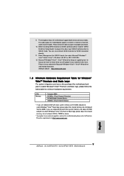
.... Before installing SATAII hard disk to SATAII connector, please read the "SATAII Hard Disk Setup Guide" on this motherboard and plan to Premium Discrete requirement at http://www.asrock.com English 9 ASRock ALiveNF6G-DVI / ALiveNF6G-VSTA Motherboard ASRock website http://www.asrock.com 1.3 Minimum Hardware Requirement Table for Windows® VistaTM Premium and Basic Logo For system integrators and users...
.... Before installing SATAII hard disk to SATAII connector, please read the "SATAII Hard Disk Setup Guide" on this motherboard and plan to Premium Discrete requirement at http://www.asrock.com English 9 ASRock ALiveNF6G-DVI / ALiveNF6G-VSTA Motherboard ASRock website http://www.asrock.com 1.3 Minimum Hardware Requirement Table for Windows® VistaTM Premium and Basic Logo For system integrators and users...
Quick Installation Guide
Page 10
...Step 3. When the CPU is locked. DO NOT force the CPU into the screw holes to secure the motherboard to the instruction manuals of your motherboard directly on a grounded antstatic pad or in place. The lever clicks on the socket while you handle components... chassis, please do not over-tighten the screws! To avoid damaging the motherboard components due to the motherboard, peripherals, and/or components. 2. Install CPU fan and heatsink. English 10 ASRock ALiveNF6G-DVI / ALiveNF6G-VSTA Motherboard Unplug the power cord from the wall socket before you push down the socket...
...Step 3. When the CPU is locked. DO NOT force the CPU into the screw holes to secure the motherboard to the instruction manuals of your motherboard directly on a grounded antstatic pad or in place. The lever clicks on the socket while you handle components... chassis, please do not over-tighten the screws! To avoid damaging the motherboard components due to the motherboard, peripherals, and/or components. 2. Install CPU fan and heatsink. English 10 ASRock ALiveNF6G-DVI / ALiveNF6G-VSTA Motherboard Unplug the power cord from the wall socket before you push down the socket...
Quick Installation Guide
Page 11
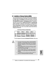
...either in the set of yellow slots (DDRII_1 and DDRII_2), or in all four slots. You may be activated. English 11 ASRock ALiveNF6G-DVI / ALiveNF6G-VSTA Motherboard see p.2/p.3 No.6) or identical DDRII DIMM pair in all four slots. 1. Populated Populated (3)* Populated Populated Populated Populated * ...For the configuration (3), please install identical DDRII DIMMs in the set of Memory Modules (DIMM) This motherboard provides four 240-pin DDRII (Double Data Rate II) DIMM slots, and supports Dual Channel Memory Technology. For dual channel ...
...either in the set of yellow slots (DDRII_1 and DDRII_2), or in all four slots. You may be activated. English 11 ASRock ALiveNF6G-DVI / ALiveNF6G-VSTA Motherboard see p.2/p.3 No.6) or identical DDRII DIMM pair in all four slots. 1. Populated Populated (3)* Populated Populated Populated Populated * ...For the configuration (3), please install identical DDRII DIMMs in the set of Memory Modules (DIMM) This motherboard provides four 240-pin DDRII (Double Data Rate II) DIMM slots, and supports Dual Channel Memory Technology. For dual channel ...
Quick Installation Guide
Page 12
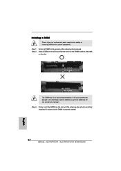
Firmly insert the DIMM into the slot at both ends fully snap back in one correct orientation. Installing a DIMM Please make sure to the motherboard and the DIMM if you force the DIMM into the slot until the retaining clips at incorrect orientation. Step 1. It will cause permanent damage to ... notch on the DIMM matches the break on the slot. Step 2. Step 3. The DIMM only fits in place and the DIMM is properly seated. 12 ASRock ALiveNF6G-DVI / ALiveNF6G-VSTA Motherboard English Unlock a DIMM slot by pressing the retaining clips outward.
Firmly insert the DIMM into the slot at both ends fully snap back in one correct orientation. Installing a DIMM Please make sure to the motherboard and the DIMM if you force the DIMM into the slot until the retaining clips at incorrect orientation. Step 1. It will cause permanent damage to ... notch on the DIMM matches the break on the slot. Step 2. Step 3. The DIMM only fits in place and the DIMM is properly seated. 12 ASRock ALiveNF6G-DVI / ALiveNF6G-VSTA Motherboard English Unlock a DIMM slot by pressing the retaining clips outward.

Quick Installation Guide
Page 13
...facing the slot that the power supply is switched off or the power cord is used to insert a HDMR card (optional) with screws. 13 ASRock ALiveNF6G-DVI / ALiveNF6G-VSTA Motherboard English Step 2. Step 3. Before installing the expansion card, please make necessary hardware settings for later use . PCIE2 (PCIE x1 slot) is ... cards, such as Gigabit LAN card, SATA2 card, etc. Step 4. Fasten the card to PCIE1 (PCIE x16 slot) on this motherboard. Installing an expansion card Step 1. Align the card connector with PCIE2 slot; You can only choose either PCI Express VGA card or...
...facing the slot that the power supply is switched off or the power cord is used to insert a HDMR card (optional) with screws. 13 ASRock ALiveNF6G-DVI / ALiveNF6G-VSTA Motherboard English Step 2. Step 3. Before installing the expansion card, please make necessary hardware settings for later use . PCIE2 (PCIE x1 slot) is ... cards, such as Gigabit LAN card, SATA2 card, etc. Step 4. Fasten the card to PCIE1 (PCIE x16 slot) on this motherboard. Installing an expansion card Step 1. Align the card connector with PCIE2 slot; You can only choose either PCI Express VGA card or...
Quick Installation Guide
Page 14
... procedures for DVI-D and D-Sub ports to the DVI-D output connector of our DVI Graphics-SI card, this motherboard. DVI Graphics-SI card Step 2. Install the DVI Graphics-SI card to PCIE1 (PCIE x16 slot) on this motherboard provides independent display controllers for proper installation of DVI Graphics-SI card 14 ASRock ALiveNF6G-DVI / ALiveNF6G-VSTA Motherboard 2.4 Easy Dual Monitor Feature (ALiveNF6G-DVI) This motherboard supports Dual...
... procedures for DVI-D and D-Sub ports to the DVI-D output connector of our DVI Graphics-SI card, this motherboard. DVI Graphics-SI card Step 2. Install the DVI Graphics-SI card to PCIE1 (PCIE x16 slot) on this motherboard provides independent display controllers for proper installation of DVI Graphics-SI card 14 ASRock ALiveNF6G-DVI / ALiveNF6G-VSTA Motherboard 2.4 Easy Dual Monitor Feature (ALiveNF6G-DVI) This motherboard supports Dual...
Quick Installation Guide
Page 15
... on the two monitors you can drive same or different display contents English 15 ASRock ALiveNF6G-DVI / ALiveNF6G-VSTA Motherboard Step 3. Independent display controllers for DVI-D and D-Sub ports to support dual VGA output: DVI-D and D-sub ports can freely enjoy the benefits of this motherboard after your system already, you install. Step 4. If you have installed NVIDIA®...
... on the two monitors you can drive same or different display contents English 15 ASRock ALiveNF6G-DVI / ALiveNF6G-VSTA Motherboard Step 3. Independent display controllers for DVI-D and D-Sub ports to support dual VGA output: DVI-D and D-sub ports can freely enjoy the benefits of this motherboard after your system already, you install. Step 4. If you have installed NVIDIA®...
Quick Installation Guide
Page 16
...", [Auto], will be your card, one , two, and three. 16 ASRock ALiveNF6G-DVI / ALiveNF6G-VSTA Motherboard English Click the "Identify" button to your system. C. Click "Extend my Windows desktop onto this motherboard. 4. G. Install the NVIDIA® PCI Express VGA card to page 13 for...the diaplay icon identified by the number 2. Connect the DVI-D input monitor cable to this monitor". Set up a multi monitor environment: 1. Boot your system. 2.5 Easy Multi Monitor Feature (ALiveNF6G-DVI / ALiveNF6G-VSTA) This motherboard supports Multi Monitor upgrade. With the internal onboard VGA...
...", [Auto], will be your card, one , two, and three. 16 ASRock ALiveNF6G-DVI / ALiveNF6G-VSTA Motherboard English Click the "Identify" button to your system. C. Click "Extend my Windows desktop onto this motherboard. 4. G. Install the NVIDIA® PCI Express VGA card to page 13 for...the diaplay icon identified by the number 2. Connect the DVI-D input monitor cable to this monitor". Set up a multi monitor environment: 1. Boot your system. 2.5 Easy Multi Monitor Feature (ALiveNF6G-DVI / ALiveNF6G-VSTA) This motherboard supports Multi Monitor upgrade. With the internal onboard VGA...
Quick Installation Guide
Page 17
.... After waiting for 15 seconds, use . However, please do the clear-CMOS action. Clear CMOS Jumper (CLRCMOS1) (see p.2/p.3, No. 1) +5VSB (standby) for 5 seconds. English 17 ASRock ALiveNF6G-DVI / ALiveNF6G-VSTA Motherboard Click and drag the display icons to enable (see p.2/p.3, No. 24) Default Clear CMOS Note: CLRCMOS1 allows you update the BIOS. Short Open Jumper Setting...
.... After waiting for 15 seconds, use . However, please do the clear-CMOS action. Clear CMOS Jumper (CLRCMOS1) (see p.2/p.3, No. 1) +5VSB (standby) for 5 seconds. English 17 ASRock ALiveNF6G-DVI / ALiveNF6G-VSTA Motherboard Click and drag the display icons to enable (see p.2/p.3, No. 24) Default Clear CMOS Note: CLRCMOS1 allows you update the BIOS. Short Open Jumper Setting...
Quick Installation Guide
Page 18
...Please refer to Pin1 Note: Make sure the red-striped side of the cable is plugged into Pin1 side of the power supply. 18 ASRock ALiveNF6G-DVI / ALiveNF6G-VSTA Motherboard English Serial ATA (SATA) Power Cable (Optional) connect to the SATA HDD power connector connect to the power supply Please connect the black... end of the SATA data cable can be connected to the power connector on the motherboard. Serial ATA (SATA) Data Cable (Optional) Either end of SATA power cable to the SATA / SATAII hard disk or the SATAII ...
...Please refer to Pin1 Note: Make sure the red-striped side of the cable is plugged into Pin1 side of the power supply. 18 ASRock ALiveNF6G-DVI / ALiveNF6G-VSTA Motherboard English Serial ATA (SATA) Power Cable (Optional) connect to the SATA HDD power connector connect to the power supply Please connect the black... end of the SATA data cable can be connected to the power connector on the motherboard. Serial ATA (SATA) Data Cable (Optional) Either end of SATA power cable to the SATA / SATAII hard disk or the SATAII ...
Quick Installation Guide
Page 19
...-ROM, TV tuner card, or MPEG card. Connect Mic_IN (MIC) to function correctly. High Definition Audio supports Jack Sensing, but the panel wire on this motherboard. Each USB 2.0 header can support two USB 2.0 ports. (9-pin USB4_5) (see p.2/p.3 No. 20) Infrared Module Header (5-pin IR1) (see p.2/p.3 No. 8) Internal Audio Connectors (4-pin CD1... header supports an optional wireless transmitting and receiving infrared module. This connector allows you use AC'97 audio panel, please install it to OUT2_L. 19 ASRock ALiveNF6G-DVI / ALiveNF6G-VSTA Motherboard English
...-ROM, TV tuner card, or MPEG card. Connect Mic_IN (MIC) to function correctly. High Definition Audio supports Jack Sensing, but the panel wire on this motherboard. Each USB 2.0 header can support two USB 2.0 ports. (9-pin USB4_5) (see p.2/p.3 No. 20) Infrared Module Header (5-pin IR1) (see p.2/p.3 No. 8) Internal Audio Connectors (4-pin CD1... header supports an optional wireless transmitting and receiving infrared module. This connector allows you use AC'97 audio panel, please install it to OUT2_L. 19 ASRock ALiveNF6G-DVI / ALiveNF6G-VSTA Motherboard English

