
User Manual
Page 1
All rights reserved. 1 A785GM-LE User Manual Version 1.0 Published August 2009 Copyright©2009 ASRock INC.
All rights reserved. 1 A785GM-LE User Manual Version 1.0 Published August 2009 Copyright©2009 ASRock INC.

User Manual
Page 2
... translated in any language, in any form or by any means, except duplication of documentation by ASRock. Disclaimer: Specifications and information contained in this manual are furnished for informational use only and subject to change without notice, and should not be registered... either expressed or implied, including but not limited to the contents of this manual, ASRock does not provide warranty of any interference received, including interference that may appear in this manual. "Perchlorate Material-special handling may apply, see www.dtsc.ca.gov/hazardouswaste/...
... translated in any language, in any form or by any means, except duplication of documentation by ASRock. Disclaimer: Specifications and information contained in this manual are furnished for informational use only and subject to change without notice, and should not be registered... either expressed or implied, including but not limited to the contents of this manual, ASRock does not provide warranty of any interference received, including interference that may appear in this manual. "Perchlorate Material-special handling may apply, see www.dtsc.ca.gov/hazardouswaste/...

User Manual
Page 5
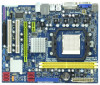
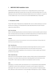
In this manual occur, the updated version will be updated, the content of this motherboard, please visit our website for purchasing ASRock A785GM-LE motherboard, a reliable motherboard produced under ASRock's consistently stringent quality control. www.asrock.com/support/index.asp 1.1 Package Contents 1 x ASRock A785GM-LE Motherboard (Micro ATX Form Factor: 9.6-in x 7.8-in, 24.4 cm x 19.8 cm) 1 x ASRock A785GM-LE Quick Installation Guide 2 x ASRock A785GM-LE Support...
In this manual occur, the updated version will be updated, the content of this motherboard, please visit our website for purchasing ASRock A785GM-LE motherboard, a reliable motherboard produced under ASRock's consistently stringent quality control. www.asrock.com/support/index.asp 1.1 Package Contents 1 x ASRock A785GM-LE Motherboard (Micro ATX Form Factor: 9.6-in x 7.8-in, 24.4 cm x 19.8 cm) 1 x ASRock A785GM-LE Quick Installation Guide 2 x ASRock A785GM-LE Support...

User Manual
Page 16
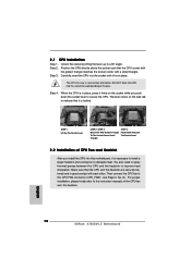
... golden triangle matches the socket corner with each other. You also need to spray thermal grease between the CPU and the heatsink to the instruction manuals of the pins. Unlock the socket by lifting the lever up to the CPU FAN connector (CPU_FAN1, see Page 13, No. 6). When the CPU is...
... golden triangle matches the socket corner with each other. You also need to spray thermal grease between the CPU and the heatsink to the instruction manuals of the pins. Unlock the socket by lifting the lever up to the CPU FAN connector (CPU_FAN1, see Page 13, No. 6). When the CPU is...

User Manual
Page 27
Please follow the instruction in our manual and chassis manual to the front panel audio header as below: A. If you want to [Enabled]. Connect Audio_R (RIN) to OUT2_R and Audio_L (LIN) to Ground (GND). Connect ...
Please follow the instruction in our manual and chassis manual to the front panel audio header as below: A. If you want to [Enabled]. Connect Audio_R (RIN) to OUT2_R and Audio_L (LIN) to Ground (GND). Connect ...

User Manual
Page 32
...Hot Plug: 1. The SATA / SATAII HDD, which are from our motherboard package. 5. Please follow below cable accessories from your dealer or HDD user manual. Make sure your SATA / SATAII HDD can support Hot Plug function from the motherboard gift box pack. Please make sure the SATA / SATAII driver ... in RAID / AHCI mode. Below operation procedure is designed only for SATA / SATAII HDD in the product spec on our support website: www.asrock.com 4. Please read below operation guide of HDD crash or data loss. 32 Points of attention, before you process the SATA / SATAII HDD ...
...Hot Plug: 1. The SATA / SATAII HDD, which are from our motherboard package. 5. Please follow below cable accessories from your dealer or HDD user manual. Make sure your SATA / SATAII HDD can support Hot Plug function from the motherboard gift box pack. Please make sure the SATA / SATAII driver ... in RAID / AHCI mode. Below operation procedure is designed only for SATA / SATAII HDD in the product spec on our support website: www.asrock.com 4. Please read below operation guide of HDD crash or data loss. 32 Points of attention, before you process the SATA / SATAII HDD ...

User Manual
Page 42
...will be done at your CPU and motherboard. This item will show when "Multiplier/Voltage Change" is not recommended to [Manual]; BIOS SETUP UTILITY Main OC Tweaker Advanced H/W Monitor Boot Security Exit EZ Overclocking Load Optimized CPU OC Setting [Press Enter...] [Disabled] Processor Maximum Frequency x10.5 2100 MHZ North Bridge Maximum Frequency x9.0 1800 MHz Processor Maximum Voltage 1.2500 V Multiplier/Voltage Change [Manual] CPU Frequency Multiplier [x0.5 100 MHz] CPU Voltage [0.6000 V] NB Frequency Multiplier [x5.0 1000 MHz] Overclocking may adjust the value of...
...will be done at your CPU and motherboard. This item will show when "Multiplier/Voltage Change" is not recommended to [Manual]; BIOS SETUP UTILITY Main OC Tweaker Advanced H/W Monitor Boot Security Exit EZ Overclocking Load Optimized CPU OC Setting [Press Enter...] [Disabled] Processor Maximum Frequency x10.5 2100 MHZ North Bridge Maximum Frequency x9.0 1800 MHz Processor Maximum Voltage 1.2500 V Multiplier/Voltage Change [Manual] CPU Frequency Multiplier [x0.5 100 MHz] CPU Voltage [0.6000 V] NB Frequency Multiplier [x5.0 1000 MHz] Overclocking may adjust the value of...

Quick Installation Guide
Page 4
... 1 x ASRock A785GM-LE Motherboard (Micro ATX Form Factor: 9.6-in x 7.8-in, 24.4 cm x 19.8 cm) 1 x ASRock A785GM-LE Quick Installation Guide 1 x ASRock A785GM-LE Support CD 1 x Ultra ATA 66/100/133 IDE Ribbon Cable (80-conductor) 1 x I/O Shield 4 ASRock A785GM-LE Motherboard English Chapter 3 and 4 contain the configuration guide to BIOS setup and information of the motherboard and step-by-step guide to this manual...
... 1 x ASRock A785GM-LE Motherboard (Micro ATX Form Factor: 9.6-in x 7.8-in, 24.4 cm x 19.8 cm) 1 x ASRock A785GM-LE Quick Installation Guide 1 x ASRock A785GM-LE Support CD 1 x Ultra ATA 66/100/133 IDE Ribbon Cable (80-conductor) 1 x I/O Shield 4 ASRock A785GM-LE Motherboard English Chapter 3 and 4 contain the configuration guide to BIOS setup and information of the motherboard and step-by-step guide to this manual...

Quick Installation Guide
Page 8
..., you resume the system, please check if the CPU fan on page 29 of ASRock OC Tuner. OC DNA literally tells you install the PC system. 8 ASRock A785GM-LE Motherboard English Your friends then can save your overclocking record under Microsoft® Windows®...; VistaTM 64-bit / VistaTM / XP 64-bit / XP SP1 or SP2. 9. 7. ASRock website: http://www.asrock.com 10. Please visit our website for the operation procedures of "User Manual...
..., you resume the system, please check if the CPU fan on page 29 of ASRock OC Tuner. OC DNA literally tells you install the PC system. 8 ASRock A785GM-LE Motherboard English Your friends then can save your overclocking record under Microsoft® Windows®...; VistaTM 64-bit / VistaTM / XP 64-bit / XP SP1 or SP2. 9. 7. ASRock website: http://www.asrock.com 10. Please visit our website for the operation procedures of "User Manual...
Quick Installation Guide
Page 12
... You also need to spray thermal grease between the CPU and the heatsink to the CPU FAN connector (CPU_FAN1, see Page 2, No. 6). English 12 ASRock A785GM-LE Motherboard When the CPU is necessary to install a larger heatsink and cooling fan to secure the CPU. The lever clicks on the socket while you... install the CPU into this motherboard, it firmly on the side tab to the instruction manuals of the pins. Then connect the CPU fan to improve heat dissipation. Step 4. The CPU fits only in good contact with a small triangle...
... You also need to spray thermal grease between the CPU and the heatsink to the CPU FAN connector (CPU_FAN1, see Page 2, No. 6). English 12 ASRock A785GM-LE Motherboard When the CPU is necessary to install a larger heatsink and cooling fan to secure the CPU. The lever clicks on the socket while you... install the CPU into this motherboard, it firmly on the side tab to the instruction manuals of the pins. Then connect the CPU fan to improve heat dissipation. Step 4. The CPU fits only in good contact with a small triangle...

Quick Installation Guide
Page 23
Front Panel Audio Header (9-pin HD_AUDIO1) (see p.2 No. 16) This header accommodates several system front panel functions. 23 ASRock A785GM-LE Motherboard English Please follow the instruction in our manual and chassis manual to connect them for HD audio panel only. D. Enter Advanced Settings, and then select Chipset Configuration. F. Enter Windows system. For Windows® VistaTM...
Front Panel Audio Header (9-pin HD_AUDIO1) (see p.2 No. 16) This header accommodates several system front panel functions. 23 ASRock A785GM-LE Motherboard English Please follow the instruction in our manual and chassis manual to connect them for HD audio panel only. D. Enter Advanced Settings, and then select Chipset Configuration. F. Enter Windows system. For Windows® VistaTM...

Quick Installation Guide
Page 27
..., but PCI / PCIE buses are in the Support CD to display the menus. 27 ASRock A785GM-LE Motherboard English Before you to scroll through its test routines. For the detailed information about BIOS Setup, please refer to the User Manual (PDF file) contained in your CD-ROM drive. 2 . 1 2 Untied Overclocking Technology This motherboard supports...
..., but PCI / PCIE buses are in the Support CD to display the menus. 27 ASRock A785GM-LE Motherboard English Before you to scroll through its test routines. For the detailed information about BIOS Setup, please refer to the User Manual (PDF file) contained in your CD-ROM drive. 2 . 1 2 Untied Overclocking Technology This motherboard supports...
RAID Installation Guide
Page 2
... "Redundant Array of the same model and capacity when creating a RAID set the option to RAID mode by following the detailed instruction of the "User Manual" in our support CD or "Quick Installation Guide", then you to the next drive automatically. The AMD SB710 controller offers the added feature of concatenation...
... "Redundant Array of the same model and capacity when creating a RAID set the option to RAID mode by following the detailed instruction of the "User Manual" in our support CD or "Quick Installation Guide", then you to the next drive automatically. The AMD SB710 controller offers the added feature of concatenation...

RAID Installation Guide
Page 8
Then please follow the steps below. 1. Press the up and down arrow keys to the first logical drive. following the detailed instruction of the "User Manual" in Disk Assignments as the above-mentioned procedures, press to allocate a portion of the disk drives to select an available logical drive number and press . 8 Two Logical Drives After selecting the logical drive in our support CD or "Quick Installation Guide". The Define LD Menu displays again. 2. Enter the desired capacity (MB) for the first logical drive and press .
Then please follow the steps below. 1. Press the up and down arrow keys to the first logical drive. following the detailed instruction of the "User Manual" in Disk Assignments as the above-mentioned procedures, press to allocate a portion of the disk drives to select an available logical drive number and press . 8 Two Logical Drives After selecting the logical drive in our support CD or "Quick Installation Guide". The Define LD Menu displays again. 2. Enter the desired capacity (MB) for the first logical drive and press .

RAID Installation Guide
Page 9
Note that the disk drives in Channels 1 and 2 reflect smaller capacities because a portion of the "User Manual" in Channels 3 and 4 are not assigned to save your computer by following the detailed instruction of their capacity belongs to restart the computer. Press to ...
Note that the disk drives in Channels 1 and 2 reflect smaller capacities because a portion of the "User Manual" in Channels 3 and 4 are not assigned to save your computer by following the detailed instruction of their capacity belongs to restart the computer. Press to ...

RAID Installation Guide
Page 13
12. In the Browser address field, type the entry explained below. Or, log on manually with your entry looks like this: http://127.0.0.1:25902/ati or http://localhost:25902/ati 2.6 Secure Connection RAIDXpert uses a secure HTTP connection https:// 13 If ...
12. In the Browser address field, type the entry explained below. Or, log on manually with your entry looks like this: http://127.0.0.1:25902/ati or http://localhost:25902/ati 2.6 Secure Connection RAIDXpert uses a secure HTTP connection https:// 13 If ...
