User Manual
Page 1
A75M-HVS User Manual Version 1.1 Published June 2011 Copyright©2011 ASRock INC. All rights reserved. 1
A75M-HVS User Manual Version 1.1 Published June 2011 Copyright©2011 ASRock INC. All rights reserved. 1

User Manual
Page 2
... trademarks or copyrights of their respective companies, and are furnished for a particular purpose. With respect to the contents of this manual, ASRock does not provide warranty of any kind, either expressed or implied, including but not limited to the implied warranties or conditions... special, incidental, or consequential damages (including damages for any interference received, including interference that may appear in the manual or product. ASRock assumes no event shall ASRock, its directors, of the FCC Rules. In no responsibility for loss of pro ts, loss of business, loss...
... trademarks or copyrights of their respective companies, and are furnished for a particular purpose. With respect to the contents of this manual, ASRock does not provide warranty of any kind, either expressed or implied, including but not limited to the implied warranties or conditions... special, incidental, or consequential damages (including damages for any interference received, including interference that may appear in the manual or product. ASRock assumes no event shall ASRock, its directors, of the FCC Rules. In no responsibility for loss of pro ts, loss of business, loss...

User Manual
Page 5
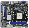
... If you for details. 5 Introduction Thank you require technical support related to the "User Manual" in , 22.6 cm x 21.6 cm) ASRock A75M-HVS Quick Installation Guide ASRock A75M-HVS Support CD 2 x Serial ATA (SATA) Data Cables (Optional) 1 x I/O Panel Shield ASRock Reminds You... 1. Because the motherboard speci cations and the BIOS software might be updated, the content of this...
... If you for details. 5 Introduction Thank you require technical support related to the "User Manual" in , 22.6 cm x 21.6 cm) ASRock A75M-HVS Quick Installation Guide ASRock A75M-HVS Support CD 2 x Serial ATA (SATA) Data Cables (Optional) 1 x I/O Panel Shield ASRock Reminds You... 1. Because the motherboard speci cations and the BIOS software might be updated, the content of this...

User Manual
Page 14
... down the socket lever to a 90o angle. Step 4. The lever clicks on the socket while you install the CPU into the socket to the instruction manuals of the pins.
... down the socket lever to a 90o angle. Step 4. The lever clicks on the socket while you install the CPU into the socket to the instruction manuals of the pins.

User Manual
Page 25
... turn off your system. 2. You may congure the way to the power switch on the chassis front panel. Please follow the instruction in our manual and chassis manual to the front panel audio header as below . If you use AC'97 audio panel, please install it to install your system using the...
... turn off your system. 2. You may congure the way to the power switch on the chassis front panel. Please follow the instruction in our manual and chassis manual to the front panel audio header as below . If you use AC'97 audio panel, please install it to install your system using the...

User Manual
Page 29
...carefully. Points of attention, before you process the SATA3 HDD Hot Plug, please check below cable accessories from your dealer or HDD user manual. The SATA3 HDD, which are from our motherboard package. 5. Please read below instructions step by the chipset because of its limitation, ... conventional power connector interface is indicated in RAID / AHCI mode. Please make sure the SATA3 driver is available on our website: www.asrock.com 2. 2.12 SATA3 HDD Hot Plug Feature and Operation Guide This motherboard supports Hot Plug feature for our motherboard, which supports SATA3...
...carefully. Points of attention, before you process the SATA3 HDD Hot Plug, please check below cable accessories from your dealer or HDD user manual. The SATA3 HDD, which are from our motherboard package. 5. Please read below instructions step by the chipset because of its limitation, ... conventional power connector interface is indicated in RAID / AHCI mode. Please make sure the SATA3 driver is available on our website: www.asrock.com 2. 2.12 SATA3 HDD Hot Plug Feature and Operation Guide This motherboard supports Hot Plug feature for our motherboard, which supports SATA3...

User Manual
Page 37
... default value for better system stability. However, it is recommended to adjust the value of this item. Multiplier/Voltage Change This item is set to [Manual], you to select enable or disable AMD Turbo Core Technology. Use this to adjust the value of Processor Frequency and Processor Voltage. 3.3 OC Tweaker Screen...
... default value for better system stability. However, it is recommended to adjust the value of this item. Multiplier/Voltage Change This item is set to [Manual], you to select enable or disable AMD Turbo Core Technology. Use this to adjust the value of Processor Frequency and Processor Voltage. 3.3 OC Tweaker Screen...

User Manual
Page 38
...Channel Memory Interleaving. RAS# to CAS# Delay (tRCD) Use this item to CAS# Delay (tRCD) Auto/Manual setting. Command Rate (CR) Use this item to change Command Rate (CR) Auto/Manual setting. The default is [Auto]. Channel Interleaving It allows you to be spread out over banks on the.... The default is [Auto]. The default is [Auto]. 38 Row Precharge Time (tRP) Use this item to change Row Precharge Time (tRP) Auto/Manual setting. RAS# Active Time (tRAS) Use this item to enable or disable DDR power down mode. The default is [Auto]. DRAM Timing Control Power ...
...Channel Memory Interleaving. RAS# to CAS# Delay (tRCD) Use this item to CAS# Delay (tRCD) Auto/Manual setting. Command Rate (CR) Use this item to change Command Rate (CR) Auto/Manual setting. The default is [Auto]. Channel Interleaving It allows you to be spread out over banks on the.... The default is [Auto]. The default is [Auto]. 38 Row Precharge Time (tRP) Use this item to change Row Precharge Time (tRP) Auto/Manual setting. RAS# Active Time (tRAS) Use this item to enable or disable DDR power down mode. The default is [Auto]. DRAM Timing Control Power ...

User Manual
Page 39
... DRAM Voltage Use this item to load and save current setting user defaults? Would you are allowed to change Refresh Cyle Time (tRFC) Auto/Manual setting. The default is [Auto]. The default is under heavy load. SB Voltage Use this item to change Write to select SB Voltage. ...Write to Read Delay (tWTR) Use this to Read Delay (tWTR) Auto/Manual setting. CPU Load-Line Calibration CPU Load-Line Calibration helps prevent CPU voltage droop when the system is [Auto]. The default value is [Auto]. ...
... DRAM Voltage Use this item to load and save current setting user defaults? Would you are allowed to change Refresh Cyle Time (tRFC) Auto/Manual setting. The default is [Auto]. The default is under heavy load. SB Voltage Use this item to change Write to select SB Voltage. ...Write to Read Delay (tWTR) Use this to Read Delay (tWTR) Auto/Manual setting. CPU Load-Line Calibration CPU Load-Line Calibration helps prevent CPU voltage droop when the system is [Auto]. The default value is [Auto]. ...

User Manual
Page 49
... speed, and the critical voltage. The default is value [Full On]. 49 Con guration options: [Full On] and [Automatic Mode]. Con guration options: [Full On], [Manual Mode] and [Automatic Mode]. 3.5 Hardware Health Event Monitoring Screen In this section, it allows you to set the CPU fan 1 speed. The default is value...
... speed, and the critical voltage. The default is value [Full On]. 49 Con guration options: [Full On] and [Automatic Mode]. Con guration options: [Full On], [Manual Mode] and [Automatic Mode]. 3.5 Hardware Health Event Monitoring Screen In this section, it allows you to set the CPU fan 1 speed. The default is value...

Quick Installation Guide
Page 4
... to this motherboard, please visit our website for details. 4 ASRock A75M-HVS Motherboard English This Quick Installation Guide contains introduction of this manual will be available on ASRock website as well. More detailed information of this manual occur, the updated version will be found in the user manual presented in our support CD for specific information...
... to this motherboard, please visit our website for details. 4 ASRock A75M-HVS Motherboard English This Quick Installation Guide contains introduction of this manual will be available on ASRock website as well. More detailed information of this manual occur, the updated version will be found in the user manual presented in our support CD for specific information...

Quick Installation Guide
Page 11
...the golden triangle matches the socket corner with each other. Step 4. For proper installation, please kindly refer to secure the CPU. English 11 ASRock A75M-HVS Motherboard Unlock the socket by lifting the lever up to improve heat dissipation. Step 2. You also need to spray thermal grease between the CPU... Socket Corner Small The Socket Lever Triangle 2.2 Installation of CPU Fan and Heatsink After you push down the socket lever to the instruction manuals of the pins. Make sure that it firmly on the side tab to avoid bending of the CPU fan and the heatsink....
...the golden triangle matches the socket corner with each other. Step 4. For proper installation, please kindly refer to secure the CPU. English 11 ASRock A75M-HVS Motherboard Unlock the socket by lifting the lever up to improve heat dissipation. Step 2. You also need to spray thermal grease between the CPU... Socket Corner Small The Socket Lever Triangle 2.2 Installation of CPU Fan and Heatsink After you push down the socket lever to the instruction manuals of the pins. Make sure that it firmly on the side tab to avoid bending of the CPU fan and the heatsink....

Quick Installation Guide
Page 22
... Jack Sensing, but the panel wire on the chassis to this header according to MIC2_L. Please follow the instruction in our manual and chassis manual to install your system using the power switch. Connect Mic_IN (MIC) to the pin assignments below : A. C. English Connect...) This header accommodates several system front panel functions. Connect Audio_R (RIN) to OUT2_R and Audio_L (LIN) to perform a normal restart. 22 ASRock A75M-HVS Motherboard System Panel Header (9-pin PANEL1) (see p.2 No. 22) 1 GND IRTX IRRX ATX+5VSB This header supports an optional wireless transmitting and...
... Jack Sensing, but the panel wire on the chassis to this header according to MIC2_L. Please follow the instruction in our manual and chassis manual to install your system using the power switch. Connect Mic_IN (MIC) to the pin assignments below : A. C. English Connect...) This header accommodates several system front panel functions. Connect Audio_R (RIN) to OUT2_R and Audio_L (LIN) to perform a normal restart. 22 ASRock A75M-HVS Motherboard System Panel Header (9-pin PANEL1) (see p.2 No. 22) 1 GND IRTX IRRX ATX+5VSB This header supports an optional wireless transmitting and...

Quick Installation Guide
Page 27
...-bit / VistaTM / VistaTM 64-bit / XP SP3 / XP 64-bit. If you wish to display the menus. 27 ASRock A75M-HVS Motherboard English For the detailed information about BIOS Setup, please refer to the User Manual (PDF file) contained in the Support CD to enter BIOS Setup after POST, please restart the system...
...-bit / VistaTM / VistaTM 64-bit / XP SP3 / XP 64-bit. If you wish to display the menus. 27 ASRock A75M-HVS Motherboard English For the detailed information about BIOS Setup, please refer to the User Manual (PDF file) contained in the Support CD to enter BIOS Setup after POST, please restart the system...

RAID Installation Guide
Page 3
... RAID 0 function can start to use the Option ROM to configure RAID. 1.1 Introduction to configure RAID functions by following the detailed instruction of the "User Manual" in a RAID 10 solution for "Redundant Array of drives. 3 The controller combines the performance of data striping (RAID 0) and the fault tolerance of the same...
... RAID 0 function can start to use the Option ROM to configure RAID. 1.1 Introduction to configure RAID functions by following the detailed instruction of the "User Manual" in a RAID 10 solution for "Redundant Array of drives. 3 The controller combines the performance of data striping (RAID 0) and the fault tolerance of the same...

RAID Installation Guide
Page 19
... drives go Offline when a physical drive fails. A RAID Ready logical drive disappears from the user interface when its physical drive fails. See the RAIDXpert User Manual for more information. 19
... drives go Offline when a physical drive fails. A RAID Ready logical drive disappears from the user interface when its physical drive fails. See the RAIDXpert User Manual for more information. 19

RAID Installation Guide
Page 23
... Host PC's IP address 127.0.0.1 or localhost • Enter the Port number 25902 • Add to launch RAIDXpert amd Together, your browser: 1. Or, log on manually with your entry looks like this: http://127.0.0.1:25902/ati or http://localhost:25902/ati 2.6 Secure Connection RAIDXpert uses a secure HTTP connection https:// 23 If...
... Host PC's IP address 127.0.0.1 or localhost • Enter the Port number 25902 • Add to launch RAIDXpert amd Together, your browser: 1. Or, log on manually with your entry looks like this: http://127.0.0.1:25902/ati or http://localhost:25902/ati 2.6 Secure Connection RAIDXpert uses a secure HTTP connection https:// 23 If...
