RAID Installation Guide
Page 2
Guide to Serial ATA (SATA) Hard Disks Installation of "U ser Manual " in the support CD. For SATA installation guide, please refer to SATA Hard Disks Installation 1.1 Serial ATA (SATA) Hard Disks Installation This motherboard adopts nVidia nForce3 chipset that supports Serial ATA (SATA) hard disks with RAID functions, including RAID 0, RAID 1, and JBOD. This section will guide you how to create RAID on this motherboard for internal storage devices. You may install SATA hard disks on SATA ports. 2 1.
Guide to Serial ATA (SATA) Hard Disks Installation of "U ser Manual " in the support CD. For SATA installation guide, please refer to SATA Hard Disks Installation 1.1 Serial ATA (SATA) Hard Disks Installation This motherboard adopts nVidia nForce3 chipset that supports Serial ATA (SATA) hard disks with RAID functions, including RAID 0, RAID 1, and JBOD. This section will guide you how to create RAID on this motherboard for internal storage devices. You may install SATA hard disks on SATA ports. 2 1.
RAID Installation Guide
Page 4
WARNING!! Hot-Plug any fault tolerance. For optimal performance, please install identical drives of RAID This motherboard adopts nVidia nForce3 chipset that optimizes two identical hard disk drives to read and write data in parallel, interleaved stacks. Although RAID 0 function can improve ...
WARNING!! Hot-Plug any fault tolerance. For optimal performance, please install identical drives of RAID This motherboard adopts nVidia nForce3 chipset that optimizes two identical hard disk drives to read and write data in parallel, interleaved stacks. Although RAID 0 function can improve ...

User Manual
Page 3
... 2.9 Serial ATA (SATA) / Serial ATAII (SATAII) Hard Disks Installation 23 2.10 Hot Plug and Hot Swap Functions for Windows® VistaTM Premium and Basic Logo 9 1.4 Motherboard Layout 10 1.5 HD 8CH I/O 11 2 . BIOS SETUP UTILITY 26 3.1 Introduction 26 3.1.1 BIOS Menu Bar 26 3.1.2 Navigation Keys 27 3.2 Main Screen 27 3.3 Advanced Screen 28 3.3.1 CPU...
... 2.9 Serial ATA (SATA) / Serial ATAII (SATAII) Hard Disks Installation 23 2.10 Hot Plug and Hot Swap Functions for Windows® VistaTM Premium and Basic Logo 9 1.4 Motherboard Layout 10 1.5 HD 8CH I/O 11 2 . BIOS SETUP UTILITY 26 3.1 Introduction 26 3.1.1 BIOS Menu Bar 26 3.1.2 Navigation Keys 27 3.2 Main Screen 27 3.3 Advanced Screen 28 3.3.1 CPU...

User Manual
Page 5
... 1 and 2 contain introduction of the Support CD. Introduction Thank you for purchasing ASRock 939NF4G-VSTA motherboard, a reliable motherboard produced under ASRock's consistently stringent quality control. ASRock website http://www.asrock.com 1.1 Package Contents 1 x ASRock 939NF4G-VSTA Motherboard (Micro ATX Form Factor: 9.6-in x 8.8-in, 24.4 cm x 22.4 cm) 1 x ASRock 939NF4G-VSTA Quick Installation Guide 1 x ASRock 939NF4G-VSTA Support CD 1 x Ultra ATA 66/100/133 IDE Ribbon Cable (80-conductor...
... 1 and 2 contain introduction of the Support CD. Introduction Thank you for purchasing ASRock 939NF4G-VSTA motherboard, a reliable motherboard produced under ASRock's consistently stringent quality control. ASRock website http://www.asrock.com 1.1 Package Contents 1 x ASRock 939NF4G-VSTA Motherboard (Micro ATX Form Factor: 9.6-in x 8.8-in, 24.4 cm x 22.4 cm) 1 x ASRock 939NF4G-VSTA Quick Installation Guide 1 x ASRock 939NF4G-VSTA Support CD 1 x Ultra ATA 66/100/133 IDE Ribbon Cable (80-conductor...

User Manual
Page 8
...than the recommended CPU bus frequencies may cause the instability of memory modules on page 11 for details. 2. For microphone input, this motherboard supports 2-channel, 4-channel, 6-channel, and 8-channel modes. Besides, you implement Dual Channel Memory Technology, make sure to enable AMD's...technology under Microsoft® Windows® VistaTM / XP 64-bit / XP SP1 or SP2 / 2000 SP4. 9. ASRock website http://www.asrock.com 8 For audio output, this motherboard supports both stereo and mono modes. You can support AMD's Cool 'n' QuietTM technology, please check AMD's website for...
...than the recommended CPU bus frequencies may cause the instability of memory modules on page 11 for details. 2. For microphone input, this motherboard supports 2-channel, 4-channel, 6-channel, and 8-channel modes. Besides, you implement Dual Channel Memory Technology, make sure to enable AMD's...technology under Microsoft® Windows® VistaTM / XP 64-bit / XP SP1 or SP2 / 2000 SP4. 9. ASRock website http://www.asrock.com 8 For audio output, this motherboard supports both stereo and mono modes. You can support AMD's Cool 'n' QuietTM technology, please check AMD's website for...

User Manual
Page 9
... Basic logo, please adjust the shared memory size of onboard VGA can be adjusted up to 128MB. * If you use external graphics card on this motherboard and plan to submit Windows® VistaTM Premium and Basic logo, please follow the below table for minimum hardware requirement. Please adopt the CPU, memory... of onboard VGA to 64MB. 1.3 Minimum Hardware Requirement Table for Windows® VistaTM Premium and Basic Logo For system integrators and users who purchase this motherboard, please refer to Premium Discrete requirement at http://www...
... Basic logo, please adjust the shared memory size of onboard VGA can be adjusted up to 128MB. * If you use external graphics card on this motherboard and plan to submit Windows® VistaTM Premium and Basic logo, please follow the below table for minimum hardware requirement. Please adopt the CPU, memory... of onboard VGA to 64MB. 1.3 Minimum Hardware Requirement Table for Windows® VistaTM Premium and Basic Logo For system integrators and users who purchase this motherboard, please refer to Premium Discrete requirement at http://www...

User Manual
Page 12
... the power cord from the power supply. Whenever you install the motherboard, study the configuration of the following precautions before you handle components. 3. 2. Installation 939NF4G-VSTA is detached from the wall socket before you install motherboard components or change any component. 2. Before you uninstall any component, ensure that the power is switched off or...
... the power cord from the power supply. Whenever you install the motherboard, study the configuration of the following precautions before you handle components. 3. 2. Installation 939NF4G-VSTA is detached from the wall socket before you install motherboard components or change any component. 2. Before you uninstall any component, ensure that the power is switched off or...
User Manual
Page 13
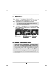
... corner with each other. Unlock the socket by lifting the lever up to avoid bending of the pins. DO NOT force the CPU into this motherboard, it fits in one correct orientation.
... corner with each other. Unlock the socket by lifting the lever up to avoid bending of the pins. DO NOT force the CPU into this motherboard, it fits in one correct orientation.

User Manual
Page 14
... identical DDR DIMMs in all four slots. 1. see p.10 No.7), so that Dual Channel Memory Technology can be activated. This motherboard also allows you have to activate the Dual Channel Memory Technology . 14 Populated Populated (3)* Populated Populated Populated Populated * For the configuration...or in Dual Channel B (DDR3 and DDR4; If you always need to install them either in the set of Memory Modules (DIMM) 939NF4G-VSTA motherboard provides four 184-pin DDR (Double Data Rate) DIMM slots, and supports Dual Channel Memory Technology. 2.3 Installation of black slots (DDR3...
... identical DDR DIMMs in all four slots. 1. see p.10 No.7), so that Dual Channel Memory Technology can be activated. This motherboard also allows you have to activate the Dual Channel Memory Technology . 14 Populated Populated (3)* Populated Populated Populated Populated * For the configuration...or in Dual Channel B (DDR3 and DDR4; If you always need to install them either in the set of Memory Modules (DIMM) 939NF4G-VSTA motherboard provides four 184-pin DDR (Double Data Rate) DIMM slots, and supports Dual Channel Memory Technology. 2.3 Installation of black slots (DDR3...

User Manual
Page 15
Unlock a DIMM slot by pressing the retaining clips outward. Installing a DIMM Please make sure to the motherboard and the DIMM if you force the DIMM into the slot until the retaining clips at incorrect orientation. Step 3. It will cause permanent damage to ...
Unlock a DIMM slot by pressing the retaining clips outward. Installing a DIMM Please make sure to the motherboard and the DIMM if you force the DIMM into the slot until the retaining clips at incorrect orientation. Step 3. It will cause permanent damage to ...

User Manual
Page 16
...unplugged. Step 3. Align the card connector with x16 lane width graphics cards. Replace the system cover. 2.5 Easy Multi Monitor Feature This motherboard supports Multi Monitor upgrade. Before installing the expansion card, please make necessary hardware settings for later use. Fasten the card to enable ... to use . PCIE2 (PCIE x1 slot) is used to insert an ASRock HDMR card with v.92 Modem functionality. PCI Slots: PCI slots are 2 PCI Express slots, 2 PCI slots and 1 HDMR slot on 939NF4G-VSTA motherboard. The HDMR slot is [Auto], which will disable onboard VGA function when...
...unplugged. Step 3. Align the card connector with x16 lane width graphics cards. Replace the system cover. 2.5 Easy Multi Monitor Feature This motherboard supports Multi Monitor upgrade. Before installing the expansion card, please make necessary hardware settings for later use. Fasten the card to enable ... to use . PCIE2 (PCIE x1 slot) is used to insert an ASRock HDMR card with v.92 Modem functionality. PCI Slots: PCI slots are 2 PCI Express slots, 2 PCI slots and 1 HDMR slot on 939NF4G-VSTA motherboard. The HDMR slot is [Auto], which will disable onboard VGA function when...

User Manual
Page 17
... jumpers are "Short" when jumper cap is "Open". If no jumper cap is placed on pins, the jumper is plugged into Pin1 side of the motherboard! • Floppy Connector (33-pin FLOPPY1) (see p.10, No. 19) 1_2 2_3 Default Clear CMOS Note: CLRCMOS1 allows you update the BIOS. Clear CMOS Jumper...
... jumpers are "Short" when jumper cap is "Open". If no jumper cap is placed on pins, the jumper is plugged into Pin1 side of the motherboard! • Floppy Connector (33-pin FLOPPY1) (see p.10, No. 19) 1_2 2_3 Default Clear CMOS Note: CLRCMOS1 allows you update the BIOS. Clear CMOS Jumper...

User Manual
Page 18
...the primary IDE connector (IDE1, blue) and CD-ROM to support 2 additional USB 2.0 ports. 18 Please refer to the power connector on the motherboard. Serial ATA II Connectors (SATA II_1: see p.10, No. 13) (SATA II_2: see p.10, No. 12) SATAII_2 SATAII_1 These Serial ATA... ports. USB 2.0 Header (9-pin USB67) (see p.10 No. 17) USB_PWR P-7 P+7 GND DUMMY 1 GND P+6 P-6 USB_PWR This HD 8CH I /O panel are not sufficient, this motherboard, please set the IDE device as "Master". Primary IDE Connector (Blue) (39-pin IDE1, see p.10 No. 9) Secondary IDE Connector (Black) (39-pin IDE2, see...
...the primary IDE connector (IDE1, blue) and CD-ROM to support 2 additional USB 2.0 ports. 18 Please refer to the power connector on the motherboard. Serial ATA II Connectors (SATA II_1: see p.10, No. 13) (SATA II_2: see p.10, No. 12) SATAII_2 SATAII_1 These Serial ATA... ports. USB 2.0 Header (9-pin USB67) (see p.10 No. 17) USB_PWR P-7 P+7 GND DUMMY 1 GND P+6 P-6 USB_PWR This HD 8CH I /O panel are not sufficient, this motherboard, please set the IDE device as "Master". Primary IDE Connector (Blue) (39-pin IDE1, see p.10 No. 9) Secondary IDE Connector (Black) (39-pin IDE2, see...

User Manual
Page 20
If you plan to connect the 3-Pin CPU fan to the CPU fan connector on this motherboard, please connect it is necessary to connect a power supply with ATX 12V plug to this connector. System Panel Header (9-pin PANEL1) (see p.10 No. 16) ... ATX12V1) (see p.10 No. 10) GND +12V CPU_FAN_SPEED FAN_SPEED_CONTROL Please connect the CPU fan cable to this connector and match the black wire to this motherboard provides 4-Pin CPU fan (Quiet Fan) support, the 3-Pin CPU fan still can work successfully even without the fan speed control function. Pin 1-3 Connected 3-Pin...
If you plan to connect the 3-Pin CPU fan to the CPU fan connector on this motherboard, please connect it is necessary to connect a power supply with ATX 12V plug to this connector. System Panel Header (9-pin PANEL1) (see p.10 No. 16) ... ATX12V1) (see p.10 No. 10) GND +12V CPU_FAN_SPEED FAN_SPEED_CONTROL Please connect the CPU fan cable to this connector and match the black wire to this motherboard provides 4-Pin CPU fan (Quiet Fan) support, the 3-Pin CPU fan still can work successfully even without the fan speed control function. Pin 1-3 Connected 3-Pin...

User Manual
Page 23
... configuration, it is called "Hot Swap" for the action to insert and remove the SATA / SATAII HDDs while the system is still power-on this motherboard for internal storage devices. STEP 4: Connect the other end of your system, please insert the support CD to the SATA / SATAII hard disk. 2.10 ...Hot Plug and Hot Swap Functions for SATA / SATAII HDDs This motherboard supports Hot Plug and Hot Swap functions for SATA / SATAII Devices. This section will guide you install can be auto-detected and listed on and...
... configuration, it is called "Hot Swap" for the action to insert and remove the SATA / SATAII HDDs while the system is still power-on this motherboard for internal storage devices. STEP 4: Connect the other end of your system, please insert the support CD to the SATA / SATAII hard disk. 2.10 ...Hot Plug and Hot Swap Functions for SATA / SATAII HDDs This motherboard supports Hot Plug and Hot Swap functions for SATA / SATAII Devices. This section will guide you install can be auto-detected and listed on and...

User Manual
Page 24
.../downloads/servicepacks/sp4/ spdeploy.htm#the_integrated_installation_fmay STEP 1: Make a SATA / SATAII Driver Diskette. When you will see the message on this motherboard, please follow the below steps. Insert HDMR card to install Windows® 2000, Windows® XP or Windows® XP 64-...on your SATA / SATAII HDDs with RAID functions, please follow the steps below website for boot devices selection appears. Insert the ASRock Support CD into floppy drive A: 24 Then you see these messages, Please insert a blank formatted diskette into your optical drive ...
.../downloads/servicepacks/sp4/ spdeploy.htm#the_integrated_installation_fmay STEP 1: Make a SATA / SATAII Driver Diskette. When you will see the message on this motherboard, please follow the below steps. Insert HDMR card to install Windows® 2000, Windows® XP or Windows® XP 64-...on your SATA / SATAII HDDs with RAID functions, please follow the steps below website for boot devices selection appears. Insert the ASRock Support CD into floppy drive A: 24 Then you see these messages, Please insert a blank formatted diskette into your optical drive ...
User Manual
Page 25
... and RAID Configuration", which is located in the folder at the following path: .. \Information\Manual\RAID Utility for Windows Guide 2.15 Untied Overclocking Technology This motherboard supports Untied Overclocking Technology, which means during overclocking, but PCI and PCIE buses are in the Support CD for Windows", which is located in Windows...
... and RAID Configuration", which is located in the folder at the following path: .. \Information\Manual\RAID Utility for Windows Guide 2.15 Untied Overclocking Technology This motherboard supports Untied Overclocking Technology, which means during overclocking, but PCI and PCIE buses are in the Support CD for Windows", which is located in Windows...

User Manual
Page 26
... device to locate and load the Operating System Security To set up the computer. You may also restart by pressing the reset button on the motherboard stores the BIOS SETUP UTILITY.
... device to locate and load the Operating System Security To set up the computer. You may also restart by pressing the reset button on the motherboard stores the BIOS SETUP UTILITY.

User Manual
Page 38
... the support to auto-detect; etc. if there is no USB device connected, "Auto" option will start to emulate the I/O devices of the CPU temperature, motherboard temperature, CPU fan speed, chassis fan speed, and the critical voltage. 3.3.8 USB Configuration BIOS SETUP UTILITY Advanced USB Configuration USB Controller USB 2.0 Support Legacy USB...
... the support to auto-detect; etc. if there is no USB device connected, "Auto" option will start to emulate the I/O devices of the CPU temperature, motherboard temperature, CPU fan speed, chassis fan speed, and the critical voltage. 3.3.8 USB Configuration BIOS SETUP UTILITY Advanced USB Configuration USB Controller USB 2.0 Support Legacy USB...

User Manual
Page 42
... The Drivers Menu shows the available devices drivers including ASRock Express GbL PCI Express LAN card driver if the system detects the installed devices. Refer to your CD-ROM drive. Software Support 4.1 Install Operating System This motherboard supports various Microsoft® Windows® operating systems:... "ASSETUP.EXE" from the BIN folder in this chapter for more about ASRock, welcome to activate the devices. 4.2.3 Utilities Menu The Utilities Menu shows the applications software that enhance the motherboard features. 4.2.1 Running The Support CD To begin using the support CD, ...
... The Drivers Menu shows the available devices drivers including ASRock Express GbL PCI Express LAN card driver if the system detects the installed devices. Refer to your CD-ROM drive. Software Support 4.1 Install Operating System This motherboard supports various Microsoft® Windows® operating systems:... "ASSETUP.EXE" from the BIN folder in this chapter for more about ASRock, welcome to activate the devices. 4.2.3 Utilities Menu The Utilities Menu shows the applications software that enhance the motherboard features. 4.2.1 Running The Support CD To begin using the support CD, ...

