User Manual
Page 1
880GMH/U3S3 User Manual Version 1.0 Published February 2011 Copyright©2011 ASRock INC. All rights reserved. 1
880GMH/U3S3 User Manual Version 1.0 Published February 2011 Copyright©2011 ASRock INC. All rights reserved. 1

User Manual
Page 2
... registered trademarks or copyrights of their respective companies, and are furnished for a particular purpose. With respect to the contents of this manual, ASRock does not provide warranty of any kind, either expressed or implied, including but not limited to the implied warranties or conditions of ... substance controlled in advance. Disclaimer: Specifications and information contained in this manual are used only for loss of profits, loss of business, loss of data, interruption of business and the like), even if ASRock has been advised of the possibility of such damages arising from any ...
... registered trademarks or copyrights of their respective companies, and are furnished for a particular purpose. With respect to the contents of this manual, ASRock does not provide warranty of any kind, either expressed or implied, including but not limited to the implied warranties or conditions of ... substance controlled in advance. Disclaimer: Specifications and information contained in this manual are used only for loss of profits, loss of business, loss of data, interruption of business and the like), even if ASRock has been advised of the possibility of such damages arising from any ...
User Manual
Page 5
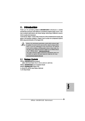
... without notice. In case any modifications of this manual occur, the updated version will be available on ASRock website as well. www.asrock.com/support/index.asp 1.1 Package Contents ASRock 880GMH/U3S3 Motherboard (Micro ATX Form Factor: 9.6-in x 9.0-in, 24.4 cm x 22.9 cm) ASRock 880GMH/U3S3 Quick Installation Guide ASRock 880GMH/U3S3 Support CD 2 x Serial ATA (SATA) Data Cables (Optional) 1 x I/O Panel Shield...
... without notice. In case any modifications of this manual occur, the updated version will be available on ASRock website as well. www.asrock.com/support/index.asp 1.1 Package Contents ASRock 880GMH/U3S3 Motherboard (Micro ATX Form Factor: 9.6-in x 9.0-in, 24.4 cm x 22.9 cm) ASRock 880GMH/U3S3 Quick Installation Guide ASRock 880GMH/U3S3 Support CD 2 x Serial ATA (SATA) Data Cables (Optional) 1 x I/O Panel Shield...
User Manual
Page 16
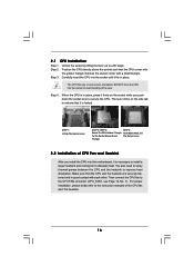
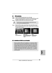
... Triangle STEP 4: Push Down And Lock The Socket Lever 2.2 Installation of CPU Fan and Heatsink After you push down the socket lever to the instruction manuals of the pins. Step 3. Make sure that it fits in one correct orientation. Step 2. DO NOT force the CPU into the socket until it is...
... Triangle STEP 4: Push Down And Lock The Socket Lever 2.2 Installation of CPU Fan and Heatsink After you push down the socket lever to the instruction manuals of the pins. Step 3. Make sure that it fits in one correct orientation. Step 2. DO NOT force the CPU into the socket until it is...
User Manual
Page 29
...® XP / XP 64-bit OS: Select "Mixer". For Windows® 7 / 7 64-bit / VistaTM / VistaTM 64-bit OS: Go to the "FrontMic" Tab in our manual and chassis manual to the front panel audio header as below: A. Connect Audio_R (RIN) to OUT2_R and Audio_L (LIN) to function correctly. E.
...® XP / XP 64-bit OS: Select "Mixer". For Windows® 7 / 7 64-bit / VistaTM / VistaTM 64-bit OS: Go to the "FrontMic" Tab in our manual and chassis manual to the front panel audio header as below: A. Connect Audio_R (RIN) to OUT2_R and Audio_L (LIN) to function correctly. E.
User Manual
Page 32
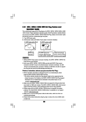
Points of Hot Plug feature carefully. Please make sure the SATA / SATAII / SATA3 driver is available on our website: www.asrock.com 2. Please follow below instructions step by the chipset because of its limitation, the SATA / SATAII / SATA3 Hot Plug support information of ... conventional power connector interface is designed only for SATA / SATAII / SATA3 HDD in the product spec on our support website: www.asrock.com 4. Make sure your dealer or HDD user manual. A. 7-pin SATA data cable B. Without SATA 15-pin power connector interface, the SATA / SATAII / SATA3 Hot Plug cannot ...
Points of Hot Plug feature carefully. Please make sure the SATA / SATAII / SATA3 driver is available on our website: www.asrock.com 2. Please follow below instructions step by the chipset because of its limitation, the SATA / SATAII / SATA3 Hot Plug support information of ... conventional power connector interface is designed only for SATA / SATAII / SATA3 HDD in the product spec on our support website: www.asrock.com 4. Make sure your dealer or HDD user manual. A. 7-pin SATA data cable B. Without SATA 15-pin power connector interface, the SATA / SATAII / SATA3 Hot Plug cannot ...

User Manual
Page 38
... the possible overclocking risk before you enable Untied Overclocking function, please enter "Overclock Mode" option of UEFI setup to set the selection from [Auto] to [Manual]. Before you apply Untied Overclocking Technology. 38
... the possible overclocking risk before you enable Untied Overclocking function, please enter "Overclock Mode" option of UEFI setup to set the selection from [Auto] to [Manual]. Before you apply Untied Overclocking Technology. 38

User Manual
Page 41
...ASRock UCC ASRock UCC (Unlock CPU Core) feature simplifies AMD CPU activation. CPU Active Core Control This allows you can enjoy the upgrade CPU performance with AM3/AM3+ CPU only, and in addition, not every AM3/AM3+ CPU can set up to enjoy an instant performance boost. Configuration options: [Auto] and [Manual... boost to the quadcore CPU, and some CPU's hidden core may be malfunctioned. As long as a simple switch of the UEFI option "ASRock UCC", you can also increase L3 cache size up overclocking features. Spread Spectrum This item should always be noted that UCC feature is [Auto...
...ASRock UCC ASRock UCC (Unlock CPU Core) feature simplifies AMD CPU activation. CPU Active Core Control This allows you can enjoy the upgrade CPU performance with AM3/AM3+ CPU only, and in addition, not every AM3/AM3+ CPU can set up to enjoy an instant performance boost. Configuration options: [Auto] and [Manual... boost to the quadcore CPU, and some CPU's hidden core may be malfunctioned. As long as a simple switch of the UEFI option "ASRock UCC", you can also increase L3 cache size up overclocking features. Spread Spectrum This item should always be noted that UCC feature is [Auto...

User Manual
Page 42
..., it is set to [Auto] by default. CPU Frequency (MHz) Use this option to adjust NB frequency. Multiplier/Voltage Change This item is set to [Manual], you selecting Hyper-Transport bus speed.
..., it is set to [Auto] by default. CPU Frequency (MHz) Use this option to adjust NB frequency. Multiplier/Voltage Change This item is set to [Manual], you selecting Hyper-Transport bus speed.

User Manual
Page 43
... default is [Auto]. Min: 1N. The default is [Auto]. RAS# Active Time (tRAS) Use this item to change RAS# to CAS# Delay (tRCD) Auto/Manual setting. RAS# Cycle Time (tRC) Use this item to enable or disable DDR power down mode. DRAM Timing Control Power Down Enable Use this item... to change RAS# Cycle Time (tRC) Auto/Manual setting. Max: 2N. Command Rate (CR) Use this item to change Command Rate (CR) Auto/Manual setting. Row Precharge Time (tRP) Use this item to be spread out over banks on the same...
... default is [Auto]. Min: 1N. The default is [Auto]. RAS# Active Time (tRAS) Use this item to change RAS# to CAS# Delay (tRCD) Auto/Manual setting. RAS# Cycle Time (tRC) Use this item to enable or disable DDR power down mode. DRAM Timing Control Power Down Enable Use this item... to change RAS# Cycle Time (tRC) Auto/Manual setting. Max: 2N. Command Rate (CR) Use this item to change Command Rate (CR) Auto/Manual setting. Row Precharge Time (tRP) Use this item to be spread out over banks on the same...

User Manual
Page 44
...to change Read to enable ot disable GPU clock override. GPU Clock Override Onboard GPU Clock Override Use this item to Precharge (tRTP) Auto/Manual setting. The default value is [Auto]. NB Core Voltage Use this to select DRAM Voltage. DRAM Voltage Use this to select NB Core ...system is [Auto]. Write Recovery Time (tWR) Use this item to change Four Activate Window (tFAW) Auto/Manual setting. Four Activate Window (tFAW) Use this item to RAS Delay (tRRD) Auto/Manual setting. The default value is [Auto]. The default value is [Auto]. Refresh Cyle Time (tRFC) Use this...
...to change Read to enable ot disable GPU clock override. GPU Clock Override Onboard GPU Clock Override Use this item to Precharge (tRTP) Auto/Manual setting. The default value is [Auto]. NB Core Voltage Use this to select DRAM Voltage. DRAM Voltage Use this to select NB Core ...system is [Auto]. Write Recovery Time (tWR) Use this item to change Four Activate Window (tFAW) Auto/Manual setting. Four Activate Window (tFAW) Use this item to RAS Delay (tRRD) Auto/Manual setting. The default value is [Auto]. The default value is [Auto]. Refresh Cyle Time (tRFC) Use this...

User Manual
Page 53
... set the CPU fan 1 speed. CPU Fan 1 Setting This allows you to set the chassis fan 1 speed. Confi guration options: [Full On], [Automatic Mode] and [Manual Mode].
... set the CPU fan 1 speed. CPU Fan 1 Setting This allows you to set the chassis fan 1 speed. Confi guration options: [Full On], [Automatic Mode] and [Manual Mode].
Quick Installation Guide
Page 5
... content of this manual, chapter 1 and 2 contain introduction of the Support CD. www.asrock.com/support/index.asp 1.1 Package Contents ASRock 880GMH/U3S3 Motherboard (Micro ATX Form Factor: 9.6-in x 9.0-in, 24.4 cm x 22.9 cm) ASRock 880GMH/U3S3 Quick Installation Guide ASRock 880GMH/U3S3 Support CD 2 x Serial ATA (SATA) Data Cables (Optional) 1 x I/O Panel Shield 5 ASRock 880GMH/U3S3 Motherboard English 1. ASRock website http://www.asrock.com If you...
... content of this manual, chapter 1 and 2 contain introduction of the Support CD. www.asrock.com/support/index.asp 1.1 Package Contents ASRock 880GMH/U3S3 Motherboard (Micro ATX Form Factor: 9.6-in x 9.0-in, 24.4 cm x 22.9 cm) ASRock 880GMH/U3S3 Quick Installation Guide ASRock 880GMH/U3S3 Support CD 2 x Serial ATA (SATA) Data Cables (Optional) 1 x I/O Panel Shield 5 ASRock 880GMH/U3S3 Motherboard English 1. ASRock website http://www.asrock.com If you...
Quick Installation Guide
Page 13
DO NOT force the CPU into the socket to the instruction manuals of the CPU fan and the heatsink. The lever clicks on the socket while you install the CPU into the socket until it is necessary ... the socket by lifting the lever up to secure the CPU. Step 2. Carefully insert the CPU into this motherboard, it is locked. Step 4. English 13 ASRock 880GMH/U3S3 Motherboard
DO NOT force the CPU into the socket to the instruction manuals of the CPU fan and the heatsink. The lever clicks on the socket while you install the CPU into the socket until it is necessary ... the socket by lifting the lever up to secure the CPU. Step 2. Carefully insert the CPU into this motherboard, it is locked. Step 4. English 13 ASRock 880GMH/U3S3 Motherboard

Quick Installation Guide
Page 26
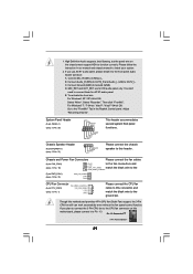
...Chassis Speaker Header (4-pin SPEAKER 1) (see p.2 No. 21) Please connect the chassis speaker to MIC2_L. Pin 1-3 Connected 3-Pin Fan Installation 26 ASRock 880GMH/U3S3 Motherboard English Connect Mic_IN (MIC) to this connector and 2 1 match the black wire to Pin 1-3. If you plan to connect the 3-Pin CPU... fan to the CPU fan connector on the chassis must support HDA to the "FrontMic" Tab in our manual and chassis manual to install your system. 2. Select "Recorder". System Panel Header (9-pin PANEL1) (see p.2 No. 1) Please connect the CPU fan 4...
...Chassis Speaker Header (4-pin SPEAKER 1) (see p.2 No. 21) Please connect the chassis speaker to MIC2_L. Pin 1-3 Connected 3-Pin Fan Installation 26 ASRock 880GMH/U3S3 Motherboard English Connect Mic_IN (MIC) to this connector and 2 1 match the black wire to Pin 1-3. If you plan to connect the 3-Pin CPU... fan to the CPU fan connector on the chassis must support HDA to the "FrontMic" Tab in our manual and chassis manual to install your system. 2. Select "Recorder". System Panel Header (9-pin PANEL1) (see p.2 No. 1) Please connect the CPU fan 4...
Quick Installation Guide
Page 30
... PCI / PCIE buses are in the fixed mode so that FSB can operate under a more stable overclocking environment. Before you apply Untied Overclocking Technology. 30 ASRock 880GMH/U3S3 Motherboard English Please refer to the warning on page 8 for the possible overclocking risk before you enable Untied Overclocking function, please enter "Overclock Mode" option... setup to set the selection from [Auto] to fixed PCI / PCIE buses. Therefore, CPU FSB is untied during overclocking, FSB enjoys better margin due to [Manual].
... PCI / PCIE buses are in the fixed mode so that FSB can operate under a more stable overclocking environment. Before you apply Untied Overclocking Technology. 30 ASRock 880GMH/U3S3 Motherboard English Please refer to the warning on page 8 for the possible overclocking risk before you enable Untied Overclocking function, please enter "Overclock Mode" option... setup to set the selection from [Auto] to fixed PCI / PCIE buses. Therefore, CPU FSB is untied during overclocking, FSB enjoys better margin due to [Manual].

Quick Installation Guide
Page 31
...-click on the system chassis. It is a menu-driven program, which allows you to display the menus. 31 ASRock 880GMH/U3S3 Motherboard English For the detailed information about BIOS Setup, please refer to the User Manual (PDF file) contained in the Support CD to scroll through its test routines. The Support CD that will...
...-click on the system chassis. It is a menu-driven program, which allows you to display the menus. 31 ASRock 880GMH/U3S3 Motherboard English For the detailed information about BIOS Setup, please refer to the User Manual (PDF file) contained in the Support CD to scroll through its test routines. The Support CD that will...

RAID Installation Guide
Page 2
... make a SATA / SATAII driver diskette, press to enter BIOS setup to set the option to RAID mode by following the detailed instruction of the "User Manual" in a RAID 10 solution for you can improve the access performance, it does not provide any HDDs of the RAID 0 Disk will double the data...
... make a SATA / SATAII driver diskette, press to enter BIOS setup to set the option to RAID mode by following the detailed instruction of the "User Manual" in a RAID 10 solution for you can improve the access performance, it does not provide any HDDs of the RAID 0 Disk will double the data...

RAID Installation Guide
Page 8
following the detailed instruction of the disk drives to the first logical drive. Two Logical Drives After selecting the logical drive in Disk Assignments as the above-mentioned procedures, press to select an available logical drive number and press . 8 Then please follow the steps below. 1. The Define LD Menu displays again. 2. Press the up and down arrow keys to allocate a portion of the "User Manual" in our support CD or "Quick Installation Guide". Enter the desired capacity (MB) for the first logical drive and press .
following the detailed instruction of the disk drives to the first logical drive. Two Logical Drives After selecting the logical drive in Disk Assignments as the above-mentioned procedures, press to select an available logical drive number and press . 8 Then please follow the steps below. 1. The Define LD Menu displays again. 2. Press the up and down arrow keys to allocate a portion of the "User Manual" in our support CD or "Quick Installation Guide". Enter the desired capacity (MB) for the first logical drive and press .

RAID Installation Guide
Page 9
... RAID level and options for the second logical drive. Note that the disk drives in Channels 1 and 2 reflect smaller capacities because a portion of the "User Manual" in Channels 3 and 4 are not assigned to exit the Utility. 6. In this example the disk drives in our support CD or "Quick Installation Guide". 9 Press...
... RAID level and options for the second logical drive. Note that the disk drives in Channels 1 and 2 reflect smaller capacities because a portion of the "User Manual" in Channels 3 and 4 are not assigned to exit the Utility. 6. In this example the disk drives in our support CD or "Quick Installation Guide". 9 Press...
