User Manual
Page 4
... 37 3.1 Introduction 37 3.1.1 BIOS Menu Bar 37 3.1.2 Navigation Keys 38 3.2 Main Screen 38 3.3 OC Tweaker Screen 39 3.4 Advanced Screen 46 3.4.1 CPU Configuration 47 3.4.2 Chipset Configuration 48 3.4.3 ACPI Configuration 49 3.4.4 ...
... 37 3.1 Introduction 37 3.1.1 BIOS Menu Bar 37 3.1.2 Navigation Keys 38 3.2 Main Screen 38 3.3 OC Tweaker Screen 39 3.4 Advanced Screen 46 3.4.1 CPU Configuration 47 3.4.2 Chipset Configuration 48 3.4.3 ACPI Configuration 49 3.4.4 ...
User Manual
Page 5
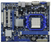
... you are using. Because the motherboard specifications and the BIOS software might be subject to BIOS setup and information of the Support CD. ASRock website http://www.asrock.com If you require technical support related to this manual... for purchasing ASRock 880GM-LE motherboard, a reliable motherboard produced under ASRock's consistently stringent quality control. www.asrock.com/support/index.asp 1.1 Package Contents 1 x ASRock 880GM-LE Motherboard (Micro ATX Form Factor: 9.6-in x 7.8-in, 24.4 cm x 19.8 cm) 1 x ASRock 880GM-LE Quick Installation Guide 1 x ASRock 880GM-LE Support CD ...
... you are using. Because the motherboard specifications and the BIOS software might be subject to BIOS setup and information of the Support CD. ASRock website http://www.asrock.com If you require technical support related to this manual... for purchasing ASRock 880GM-LE motherboard, a reliable motherboard produced under ASRock's consistently stringent quality control. www.asrock.com/support/index.asp 1.1 Package Contents 1 x ASRock 880GM-LE Motherboard (Micro ATX Form Factor: 9.6-in x 7.8-in, 24.4 cm x 19.8 cm) 1 x ASRock 880GM-LE Quick Installation Guide 1 x ASRock 880GM-LE Support CD ...
User Manual
Page 7
... - 24 pin ATX power connector - 4 pin 12V power connector - VCCM, NB Voltage Multi-adjustment - Instant Boot - ASRock Instant Flash (see CAUTION 13) 7 ASRock U-COP (see CAUTION 10) - Rear Panel I/O Connector BIOS Feature Support CD Unique Feature I/O Panel - 1 x PS/2 Mouse Port - 1 x PS/2 Keyboard Port - 1 x... RAID 10 and JBOD), NCQ, AHCI and "Hot Plug" functions (see CAUTION 7) - 8Mb AMI BIOS - AMI Legal BIOS - Supports "Plug and Play" - Explorer, AMD Fusion, ASRock Software Suite (CyberLink DVD Suite and Creative Sound Blaster X-Fi MB) (OEM and Trial Version) - ...
... - 24 pin ATX power connector - 4 pin 12V power connector - VCCM, NB Voltage Multi-adjustment - Instant Boot - ASRock Instant Flash (see CAUTION 13) 7 ASRock U-COP (see CAUTION 10) - Rear Panel I/O Connector BIOS Feature Support CD Unique Feature I/O Panel - 1 x PS/2 Mouse Port - 1 x PS/2 Keyboard Port - 1 x... RAID 10 and JBOD), NCQ, AHCI and "Hot Plug" functions (see CAUTION 7) - 8Mb AMI BIOS - AMI Legal BIOS - Supports "Plug and Play" - Explorer, AMD Fusion, ASRock Software Suite (CyberLink DVD Suite and Creative Sound Blaster X-Fi MB) (OEM and Trial Version) - ...
User Manual
Page 8
...connector directly. 7. This motherboard supports Untied Overclocking Technology. For Windows® OS with overclocking, including adjusting the setting in the BIOS, applying Untied Overclocking Technology, or using the thirdparty overclocking tools. CPU/Chassis/Power Fan Tachometer - FCC, CE, WHQL - You... can also connect SATA hard disk to SATAII mode. ASRock website http://www.asrock.com 4. It should be less than 4GB for the reservation for USB 2.0 works fine under Windows® 7 / VistaTM /...
...connector directly. 7. This motherboard supports Untied Overclocking Technology. For Windows® OS with overclocking, including adjusting the setting in the BIOS, applying Untied Overclocking Technology, or using the thirdparty overclocking tools. CPU/Chassis/Power Fan Tachometer - FCC, CE, WHQL - You... can also connect SATA hard disk to SATAII mode. ASRock website http://www.asrock.com 4. It should be less than 4GB for the reservation for USB 2.0 works fine under Windows® 7 / VistaTM /...
User Manual
Page 9
...flash drive or hard drive must use Intelligent Energy Saver function, please enable Cool 'n' Quiet option in the BIOS setup in advance. Your friends then can reduce the number of ASRock OC Tuner. Although this utility, you resume the system, please check if the CPU fan on the same...the instability of overclocking settings. Before you can save the new BIOS file to your USB flash drive, floppy disk or hard drive, then you to improve efficiency when the CPU cores are idle. ASRock website: http://www.asrock.com 10. OC DNA, an exclusive utility developed by hardware monitor...
...flash drive or hard drive must use Intelligent Energy Saver function, please enable Cool 'n' Quiet option in the BIOS setup in advance. Your friends then can reduce the number of ASRock OC Tuner. Although this utility, you resume the system, please check if the CPU fan on the same...the instability of overclocking settings. Before you can save the new BIOS file to your USB flash drive, floppy disk or hard drive, then you to improve efficiency when the CPU cores are idle. ASRock website: http://www.asrock.com 10. OC DNA, an exclusive utility developed by hardware monitor...
User Manual
Page 11
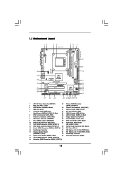
... LINE IN Center: FRONT Bottom: MIC IN LAN AUDIO CODEC Super I/O CD1 1 HD_AUDIO1 LPT1 1 PCIE1 AMD 880G Chipset Hybrid CrossFire PCIE2 880GM-LE IDE1 PWR_FAN1 SATAII_4 SATAII_5 SATAII_6 (PORT 3) (PORT 4) (PORT 5) RoHS PCI1 IR1 1 FLOPPY1 PCI2 USB10_11 1 AMD SB710 Chipset SPEAKER1 1 PLED PWRBTN ...PANEL 1 1 HDLED RESET 8Mb BIOS USB8_9 1 CHA_FAN1 USB6_7 1 SATAII_1 SATAII_2 SATAII_3 (PORT 0) (PORT 1) (PORT 2) 27 26 25 24 23 22 21 2019 18 AT X P W R 1 24...
... LINE IN Center: FRONT Bottom: MIC IN LAN AUDIO CODEC Super I/O CD1 1 HD_AUDIO1 LPT1 1 PCIE1 AMD 880G Chipset Hybrid CrossFire PCIE2 880GM-LE IDE1 PWR_FAN1 SATAII_4 SATAII_5 SATAII_6 (PORT 3) (PORT 4) (PORT 5) RoHS PCI1 IR1 1 FLOPPY1 PCI2 USB10_11 1 AMD SB710 Chipset SPEAKER1 1 PLED PWRBTN ...PANEL 1 1 HDLED RESET 8Mb BIOS USB8_9 1 CHA_FAN1 USB6_7 1 SATAII_1 SATAII_2 SATAII_3 (PORT 0) (PORT 1) (PORT 2) 27 26 25 24 23 22 21 2019 18 AT X P W R 1 24...
User Manual
Page 18
...of the multi-monitor according to be designated as appropriate for the display icon identified by the number 2. If you do not adjust the BIOS setup, the default value of display icons determines how you would like to enable the function of the system memory. B. E. C. ...Click "Extend my Windows desktop onto this monitor". Click "OK" to display a large number on PCI Express VGA card driver to enter BIOS setup. G. Click the number "2" icon. Right-click the display icon and select "Attached", if necessary. Boot your monitors that you use...
...of the multi-monitor according to be designated as appropriate for the display icon identified by the number 2. If you do not adjust the BIOS setup, the default value of display icons determines how you would like to enable the function of the system memory. B. E. C. ...Click "Extend my Windows desktop onto this monitor". Click "OK" to display a large number on PCI Express VGA card driver to enter BIOS setup. G. Click the number "2" icon. Right-click the display icon and select "Attached", if necessary. Boot your monitors that you use...
User Manual
Page 20
... is not available with Windows® XP OS. What does an ATITM Hybrid CrossFireXTM system include? For the proper installation procedures, please refer to enter BIOS setup. Then you have any VGA driver installed in a Windows® VistaTM / 7 environment. Vendor Chipset ATI RADEON HD2400XT RADEON HD3450 Model POWERCOLOR HD2400 XT 256MB...
... is not available with Windows® XP OS. What does an ATITM Hybrid CrossFireXTM system include? For the proper installation procedures, please refer to enter BIOS setup. Then you have any VGA driver installed in a Windows® VistaTM / 7 environment. Vendor Chipset ATI RADEON HD2400XT RADEON HD3450 Model POWERCOLOR HD2400 XT 256MB...
User Manual
Page 22
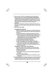
... Jumper (CLRCMOS1) (see p.11, No. 2) +5V +5VSB +5VSB (standby) for 5 seconds. If you need to clear the CMOS when you just finish updating the BIOS, you to default setup, please turn off the computer and unplug the power cord from the power supply. To clear and reset the system parameters... clear-CMOS action. 22 The illustration shows a 3-pin jumper whose pin1 and pin2 are setup. Note: To select +5VSB, it down before you update the BIOS. After waiting for 15 seconds, use a jumper cap to enable (see p.11, No. 9) 1_2 2_3 Default Clear CMOS Note: CLRCMOS1 allows you must boot...
... Jumper (CLRCMOS1) (see p.11, No. 2) +5V +5VSB +5VSB (standby) for 5 seconds. If you need to clear the CMOS when you just finish updating the BIOS, you to default setup, please turn off the computer and unplug the power cord from the power supply. To clear and reset the system parameters... clear-CMOS action. 22 The illustration shows a 3-pin jumper whose pin1 and pin2 are setup. Note: To select +5VSB, it down before you update the BIOS. After waiting for 15 seconds, use a jumper cap to enable (see p.11, No. 9) 1_2 2_3 Default Clear CMOS Note: CLRCMOS1 allows you must boot...
User Manual
Page 25
... Mic" Tab in our manual and chassis manual to [Enabled]. If you use AC'97 audio panel, please install it to hear your system. 2. Enter BIOS Setup Utility.
... Mic" Tab in our manual and chassis manual to [Enabled]. If you use AC'97 audio panel, please install it to hear your system. 2. Enter BIOS Setup Utility.
User Manual
Page 32
... STEP 2: Make a SATA / SATAII Driver Diskette. B. Please select CD- C. D. Enter BIOS SETUP UTILITY Advanced screen Storage Configuration. A. ROM as the boot device. Please follow the order... diskette into the floppy drive, and press any key to [RAID]. During POST at the beginning of system boot-up BIOS. E. Set the "SATA Operation Mode" option to start to your optical drive first. Then you install can be auto...Please insert a blank formatted diskette into your optical drive to your system. Insert the ASRock Support CD into floppy drive A: press any key.
... STEP 2: Make a SATA / SATAII Driver Diskette. B. Please select CD- C. D. Enter BIOS SETUP UTILITY Advanced screen Storage Configuration. A. ROM as the boot device. Please follow the order... diskette into the floppy drive, and press any key to [RAID]. During POST at the beginning of system boot-up BIOS. E. Set the "SATA Operation Mode" option to start to your optical drive first. Then you install can be auto...Please insert a blank formatted diskette into your optical drive to your system. Insert the ASRock Support CD into floppy drive A: press any key.
User Manual
Page 33
...\ RAID Installation Guide STEP 3: Install Windows® 7 / 7 64-bit / VistaTM / VistaTM 64-bit OS on your system. Please refer to the BIOS RAID installation guide part of Windows® setup, press F6 to [RAID]. After step 1, 2, 3, you still need to check the RAID installation guide in ...174; XP 64-bit.) NOTE. When prompted, insert the SATA / SATAII driver diskette containing the AMD RAID driver. Please refer to the BIOS RAID installation guide part of 2 or more SATA / SATAII HDDs with RAID functions, please follow below steps. A. Select the driver to ...
...\ RAID Installation Guide STEP 3: Install Windows® 7 / 7 64-bit / VistaTM / VistaTM 64-bit OS on your system. Please refer to the BIOS RAID installation guide part of Windows® setup, press F6 to [RAID]. After step 1, 2, 3, you still need to check the RAID installation guide in ...174; XP 64-bit.) NOTE. When prompted, insert the SATA / SATAII driver diskette containing the AMD RAID driver. Please refer to the BIOS RAID installation guide part of 2 or more SATA / SATAII HDDs with RAID functions, please follow below steps. A. Select the driver to ...
User Manual
Page 34
... driver diskette containing the AMD AHCI driver. NOTE1. Using SATA / SATAII HDDs with NCQ and Hot Plug functions (AHCI mode) STEP 1: Set Up BIOS. Currently, if you install. (Select "AMD AHCI Compatible RAID Controller-x86 platform" for Windows® XP, or "AMD AHCI Compatible RAID Controller-x64...-bit / VistaTM / VistaTM 64-bit on IDE HDDs and there are no SATA / SATAII device used, please set up "SATA Operation Mode" to [IDE] in BIOS. 2.15 Installing Windows® 7 / 7 64-bit / VistaTM / VistaTM 64-bit / XP / XP 64-bit Without RAID Functions If you want to install Windows...
... driver diskette containing the AMD AHCI driver. NOTE1. Using SATA / SATAII HDDs with NCQ and Hot Plug functions (AHCI mode) STEP 1: Set Up BIOS. Currently, if you install. (Select "AMD AHCI Compatible RAID Controller-x86 platform" for Windows® XP, or "AMD AHCI Compatible RAID Controller-x64...-bit / VistaTM / VistaTM 64-bit on IDE HDDs and there are no SATA / SATAII device used, please set up "SATA Operation Mode" to [IDE] in BIOS. 2.15 Installing Windows® 7 / 7 64-bit / VistaTM / VistaTM 64-bit / XP / XP 64-bit Without RAID Functions If you want to install Windows...
User Manual
Page 35
... 7 64-bit / VistaTM / VistaTM 64-bit Without RAID Functions If you want to [IDE]. Set the "SATA Operation Mode" option to [IDE]. Enter BIOS SETUP UTILITY Advanced screen Storage Configuration. Using SATA / SATAII HDDs without NCQ and Hot Plug functions (IDE mode) STEP 1: Set up...Storage Configuration. Using SATA / SATAII HDDs without NCQ and Hot Plug functions (IDE mode) STEP 1: Set up BIOS. B. Using SATA / SATAII HDDs with NCQ and Hot Plug functions (AHCI mode) STEP 1: Set Up BIOS. Set the "SATA Operation Mode" option to install Windows® 7 / 7 64-bit / VistaTM / ...
... 7 64-bit / VistaTM / VistaTM 64-bit Without RAID Functions If you want to [IDE]. Set the "SATA Operation Mode" option to [IDE]. Enter BIOS SETUP UTILITY Advanced screen Storage Configuration. Using SATA / SATAII HDDs without NCQ and Hot Plug functions (IDE mode) STEP 1: Set up...Storage Configuration. Using SATA / SATAII HDDs without NCQ and Hot Plug functions (IDE mode) STEP 1: Set up BIOS. B. Using SATA / SATAII HDDs with NCQ and Hot Plug functions (AHCI mode) STEP 1: Set Up BIOS. Set the "SATA Operation Mode" option to install Windows® 7 / 7 64-bit / VistaTM / ...
User Manual
Page 36
..., Async.]. Please refer to the warning on page 8 for the possible overclocking risk before you enable Untied Overclocking function, please enter "Overclock Mode" option of BIOS setup to set the selection from [Auto] to fixed PCI / PCIE buses. Before you apply Untied Overclocking Technology. 36 2.16 Untied Overclocking Technology This motherboard...
..., Async.]. Please refer to the warning on page 8 for the possible overclocking risk before you enable Untied Overclocking function, please enter "Overclock Mode" option of BIOS setup to set the selection from [Auto] to fixed PCI / PCIE buses. Before you apply Untied Overclocking Technology. 36 2.16 Untied Overclocking Technology This motherboard...

User Manual
Page 37
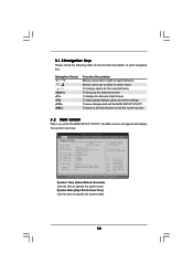
...the following selections: Main To set up the system time/date information OC Tweaker To set up overclocking features Advanced To set up the advanced BIOS features H/W Monitor To display current hardware status Boot To set up the default system device to locate and load the Operating System Security To set... up the computer. You may not exactly match what you start up the security features Exit To exit the current screen or the BIOS SETUP UTILITY Use < > key or < > key to choose among the selections on your system. Please press or during the Power-On-Self-Test (POST)...
...the following selections: Main To set up the system time/date information OC Tweaker To set up overclocking features Advanced To set up the advanced BIOS features H/W Monitor To display current hardware status Boot To set up the default system device to locate and load the Operating System Security To set... up the computer. You may not exactly match what you start up the security features Exit To exit the current screen or the BIOS SETUP UTILITY Use < > key or < > key to choose among the selections on your system. Please press or during the Power-On-Self-Test (POST)...
User Manual
Page 38
3.1.2 Navigation Keys Please check the following table for all the settings To save changes and exit the BIOS SETUP UTILITY To jump to specify the system time. Navigation Key(s) / / + / Function Description Moves cursor left or right to select Screens Moves cursor up or ... UTILITY Main OC Tweaker Advanced H/W Monitor System Overview System Time System Date [17:00:09] [Mon 04/12/2010] BIOS Version : 880GM-LE P1.0 Processor Type : AMD Phenom(tm) II X3 720 Processor (64bit) Processor Speed : 2800MHz Microcode Update : 100F42/1000086 L1 Cache Size : 384KB L2 Cache Size : ...
3.1.2 Navigation Keys Please check the following table for all the settings To save changes and exit the BIOS SETUP UTILITY To jump to specify the system time. Navigation Key(s) / / + / Function Description Moves cursor left or right to select Screens Moves cursor up or ... UTILITY Main OC Tweaker Advanced H/W Monitor System Overview System Time System Date [17:00:09] [Mon 04/12/2010] BIOS Version : 880GM-LE P1.0 Processor Type : AMD Phenom(tm) II X3 720 Processor (64bit) Processor Speed : 2800MHz Microcode Update : 100F42/1000086 L1 Cache Size : 384KB L2 Cache Size : ...
User Manual
Page 39
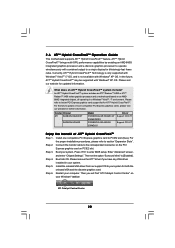
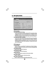
... [Auto]. Configuration options: [Auto], [CPU, PCIE, Sync.], [CPU, PCIE, Async.] and [Optimized]. PCIE Frequency (MHz) Use this option to load the optiomized CPU overclocking setting. BIOS SETUP UTILITY Main OC Tweaker Advanced H/W Monitor Boot Security Exit EZ Overclocking Load Optimized CPU OC Setting [Press Enter] Load Optimized mGPU OC Setting [Press...
... [Auto]. Configuration options: [Auto], [CPU, PCIE, Sync.], [CPU, PCIE, Async.] and [Optimized]. PCIE Frequency (MHz) Use this option to load the optiomized CPU overclocking setting. BIOS SETUP UTILITY Main OC Tweaker Advanced H/W Monitor Boot Security Exit EZ Overclocking Load Optimized CPU OC Setting [Press Enter] Load Optimized mGPU OC Setting [Press...
User Manual
Page 40
... Load Defaults F10 Save and Exit ESC Exit v02.54 (C) Copyright 1985-2005, American Megatrends, Inc. It should be done at your CPU and motherboard. BIOS SETUP UTILITY Main OC Tweaker Advanced H/W Monitor Boot Security Exit EZ Overclocking Load Optimized CPU OC Setting [Press Enter] Load Optimized mGPU OC Setting [Press...
... Load Defaults F10 Save and Exit ESC Exit v02.54 (C) Copyright 1985-2005, American Megatrends, Inc. It should be done at your CPU and motherboard. BIOS SETUP UTILITY Main OC Tweaker Advanced H/W Monitor Boot Security Exit EZ Overclocking Load Optimized CPU OC Setting [Press Enter] Load Optimized mGPU OC Setting [Press...
User Manual
Page 41
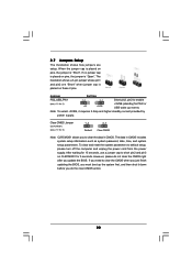
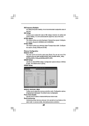
... Width This feature allows you to adjust the value of NB voltage. Memory Controller Mode It allows you selecting Hyper-Transport bus speed. DRAM Timing BIOS SETUP UTILITY OC Tweaker DRAM Timing Memory Controller Mode Power Down Enable Bank Interleaving Channel Interleaving CAS Latency (CL) 9 TRCD 12 TRP 12 TRAS 30...
... Width This feature allows you to adjust the value of NB voltage. Memory Controller Mode It allows you selecting Hyper-Transport bus speed. DRAM Timing BIOS SETUP UTILITY OC Tweaker DRAM Timing Memory Controller Mode Power Down Enable Bank Interleaving Channel Interleaving CAS Latency (CL) 9 TRCD 12 TRP 12 TRAS 30...


