User Manual
Page 9
... much quickly from App store to your USB flash drive, floppy disk or hard drive, then you to RAM (S3), hibernation mode (S4) or power off (S5). ASRock Instant Flash is a BIOS flash utility embedded in a user-friendly interface, which is including Hardware Monitor, Fan Control, Overclocking, OC DNA and IES. All you can load the OC profile to their own system to update system BIOS without sacrificing computing performance. Also, please do...
... much quickly from App store to your USB flash drive, floppy disk or hard drive, then you to RAM (S3), hibernation mode (S4) or power off (S5). ASRock Instant Flash is a BIOS flash utility embedded in a user-friendly interface, which is including Hardware Monitor, Fan Control, Overclocking, OC DNA and IES. All you can load the OC profile to their own system to update system BIOS without sacrificing computing performance. Also, please do...

User Manual
Page 11
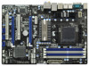
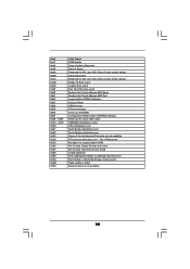
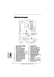
... RESET 30 29 28 27 26 25 24 23 22 21 20 30.5cm (12.0-in) 9 10 11 12 13 14 15 16 17 18 19 1 ATX 12V Power Connector (ATX12V1) 19 Chassis Speaker Header 2 Chassis Fan Connector (CHA_FAN3) (SPEAKER 1, White) 3 AM3+ CPU Socket 20 System Panel Header (PANEL1, White) 4 CPU Heatsink Retention Module 21 Power LED Header (PLED1) 5 CPU Fan Connector (CPU_FAN2) 22 Chassis Fan Connector (CHA_FAN2) 6 CPU Fan Connector (CPU_FAN1) 23 Chassis Fan Connector (CHA_FAN1) 7 2 x 240-pin DDR3 DIMM Slots 24 Clear CMOS Jumper (CLRCMOS1) (Dual Channel...
... RESET 30 29 28 27 26 25 24 23 22 21 20 30.5cm (12.0-in) 9 10 11 12 13 14 15 16 17 18 19 1 ATX 12V Power Connector (ATX12V1) 19 Chassis Speaker Header 2 Chassis Fan Connector (CHA_FAN3) (SPEAKER 1, White) 3 AM3+ CPU Socket 20 System Panel Header (PANEL1, White) 4 CPU Heatsink Retention Module 21 Power LED Header (PLED1) 5 CPU Fan Connector (CPU_FAN2) 22 Chassis Fan Connector (CHA_FAN2) 6 CPU Fan Connector (CPU_FAN1) 23 Chassis Fan Connector (CHA_FAN1) 7 2 x 240-pin DDR3 DIMM Slots 24 Clear CMOS Jumper (CLRCMOS1) (Dual Channel...
User Manual
Page 20
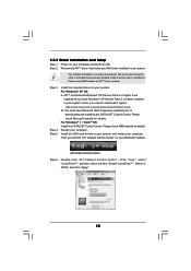
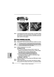
... Setup Step 1. Step 4. For Windows® 7 / VistaTM OS: Install the CATALYST Control Center. We recommend using this utility to uninstall any VGA driver installed in your system, there is an optional download. Step 3. You must have any previously installed Catalyst drivers prior to download it again): http://www.microsoft.com/windowsxp/sp2/default.mspx B. Then you have Windows® XP Service Pack 2 or higher installed in your computer. Power...
... Setup Step 1. Step 4. For Windows® 7 / VistaTM OS: Install the CATALYST Control Center. We recommend using this utility to uninstall any VGA driver installed in your system, there is an optional download. Step 3. You must have any previously installed Catalyst drivers prior to download it again): http://www.microsoft.com/windowsxp/sp2/default.mspx B. Then you have Windows® XP Service Pack 2 or higher installed in your computer. Power...
User Manual
Page 27
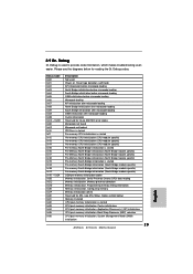
... is started Pre-memory South Bridge initialization (South Bridge module specific) Pre-memory South Bridge initialization (South Bridge module specific) Pre-memory South Bridge initialization (South Bridge module specific) OEM pre-memory initialization codes Memory initialization. Please see ASL Status Codes section below for ASL (see the diagrams below ) Memory Installed CPU post-memory initialization is used Power on. Serial Presence Detect (SPD) data reading Memory initialization. Application Processor(s) (AP) initialization CPU post-memory initialization. Configuring memory...
... is started Pre-memory South Bridge initialization (South Bridge module specific) Pre-memory South Bridge initialization (South Bridge module specific) Pre-memory South Bridge initialization (South Bridge module specific) OEM pre-memory initialization codes Memory initialization. Please see ASL Status Codes section below for ASL (see the diagrams below ) Memory Installed CPU post-memory initialization is used Power on. Serial Presence Detect (SPD) data reading Memory initialization. Application Processor(s) (AP) initialization CPU post-memory initialization. Configuring memory...
User Manual
Page 30
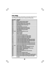
... SCSI Enable Setup Verifying Password Start of Setup Reserved for ASL (see ASL Status Codes section below) Setup Input Wait Reserved for ASL (see ASL Status Codes section below) Ready To Boot event Legacy Boot event Exit Boot Services event Runtime Set Virtual Address MAP Begin Runtime Set Virtual Address MAP End Legacy Option ROM Initialization System Reset USB hot plug PCI bus hot plug Clean-up of NVRAM Configuration Reset (reset of NVRAM settings) Reserved for future AMI codes OEM...
... SCSI Enable Setup Verifying Password Start of Setup Reserved for ASL (see ASL Status Codes section below) Setup Input Wait Reserved for ASL (see ASL Status Codes section below) Ready To Boot event Legacy Boot event Exit Boot Services event Runtime Set Virtual Address MAP Begin Runtime Set Virtual Address MAP End Legacy Option ROM Initialization System Reset USB hot plug PCI bus hot plug Clean-up of NVRAM Configuration Reset (reset of NVRAM settings) Reserved for future AMI codes OEM...
User Manual
Page 32
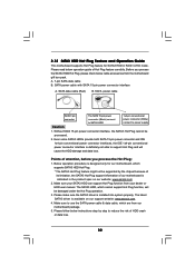
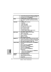
... procedure is indicated in RAID / AHCI mode. The SATA3 HDD, which are from our motherboard package. 5. SATA power cable with SATA 15-pin power connector interface A. Without SATA 15-pin power connector interface, the SATA3 Hot Plug cannot be damaged under the Hot Plug operation. 3. SATA power cable SATA 7-pin connector Caution The SATA 15-pin power connector (Black) connect to SATA3 HDD 1x4-pin conventional power connector (White) connect to use the SATA power cable & data cable, which cannot support Hot Plug function, will cause the HDD damage and data loss...
... procedure is indicated in RAID / AHCI mode. The SATA3 HDD, which are from our motherboard package. 5. SATA power cable with SATA 15-pin power connector interface A. Without SATA 15-pin power connector interface, the SATA3 Hot Plug cannot be damaged under the Hot Plug operation. 3. SATA power cable SATA 7-pin connector Caution The SATA 15-pin power connector (Black) connect to SATA3 HDD 1x4-pin conventional power connector (White) connect to use the SATA power cable & data cable, which cannot support Hot Plug function, will cause the HDD damage and data loss...
User Manual
Page 34
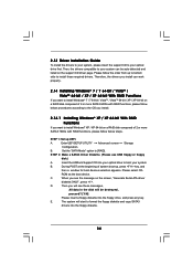
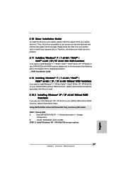
.... Enter UEFI SETUP UTILITY Advanced screen Storage Configuration. D. E. Therefore, the drivers you install can be destroyed, proceed? [Y/N] Please insert a floppy diskette into the floppy diskette. 34 STEP 1: Set up , press key, and then a window for boot devices selection appears. A. STEP 2: Make a SATA3 Driver Diskette. (Please use USB floppy or floppy disk.) A. C. 2.13 Driver Installation Guide To install the drivers to your system, please insert the support CD to install Windows® XP / XP 64-bit on a RAID disk composed of 2 or more SATA3 HDDs...
.... Enter UEFI SETUP UTILITY Advanced screen Storage Configuration. D. E. Therefore, the drivers you install can be destroyed, proceed? [Y/N] Please insert a floppy diskette into the floppy diskette. 34 STEP 1: Set up , press key, and then a window for boot devices selection appears. A. STEP 2: Make a SATA3 Driver Diskette. (Please use USB floppy or floppy disk.) A. C. 2.13 Driver Installation Guide To install the drivers to your system, please insert the support CD to install Windows® XP / XP 64-bit on a RAID disk composed of 2 or more SATA3 HDDs...
User Manual
Page 47
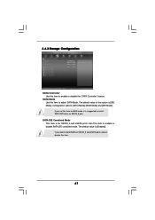
... disable the "SATA Controller" feature. SATA IDE Combined Mode This item is [Enabled]. Configuration options: [AHCI Mode], [RAID Mode] and [IDE Mode]. 3.4.3 Storage Configuration SATA Controller Use this option is [IDE Mode]. If you want to enable or disable SATA IDE combined mode. Use this item to install SATA ODD driver on SATA3_5 and eSATA ports, please disable this item. 47 The default value is for SATA3_5 and eSATA ports. SATA Mode Use this item to build RAID on SATA3_5 port. If you set this item to RAID mode, it is suggested to adjust SATA Mode...
... disable the "SATA Controller" feature. SATA IDE Combined Mode This item is [Enabled]. Configuration options: [AHCI Mode], [RAID Mode] and [IDE Mode]. 3.4.3 Storage Configuration SATA Controller Use this option is [IDE Mode]. If you want to enable or disable SATA IDE combined mode. Use this item to install SATA ODD driver on SATA3_5 and eSATA ports, please disable this item. 47 The default value is for SATA3_5 and eSATA ports. SATA Mode Use this item to build RAID on SATA3_5 port. If you set this item to RAID mode, it is suggested to adjust SATA Mode...

User Manual
Page 50
... of USB 2.0 controller. The default value is recommended to select [Disabled] to enter OS. [UEFI Setup Only] - Please refer to below descriptions for legacy USB. [Auto] - Enables legacy support if USB devices are four confi guration options: [Enabled], [Auto], [Disabled] and [UEFI Setup Only]. If you have USB compatibility issue, it is [Enabled]. There are connected. [Disabled] - 3.4.6 USB Configuration USB 2.0 Controller Use this option to select legacy support for USB devices. Legacy USB Support Use this item to enable or disable the use under UEFI setup and Windows...
... of USB 2.0 controller. The default value is recommended to select [Disabled] to enter OS. [UEFI Setup Only] - Please refer to below descriptions for legacy USB. [Auto] - Enables legacy support if USB devices are four confi guration options: [Enabled], [Auto], [Disabled] and [UEFI Setup Only]. If you have USB compatibility issue, it is [Enabled]. There are connected. [Disabled] - 3.4.6 USB Configuration USB 2.0 Controller Use this option to select legacy support for USB devices. Legacy USB Support Use this item to enable or disable the use under UEFI setup and Windows...
User Manual
Page 55
... useful utilities that the motherboard supports. or you need to contact ASRock or want to display the menus. 4.2.2 Drivers Menu The Drivers Menu shows the available devices drivers if the system detects the installed devices. 4. Please install the necessary drivers to visit ASRock's website at http://www.asrock.com; The CD automatically displays the Main Menu if "AUTORUN" is enabled in this chapter for further information. 55 Because motherboard settings and hardware options vary, use the setup...
... useful utilities that the motherboard supports. or you need to contact ASRock or want to display the menus. 4.2.2 Drivers Menu The Drivers Menu shows the available devices drivers if the system detects the installed devices. 4. Please install the necessary drivers to visit ASRock's website at http://www.asrock.com; The CD automatically displays the Main Menu if "AUTORUN" is enabled in this chapter for further information. 55 Because motherboard settings and hardware options vary, use the setup...
Quick Installation Guide
Page 2
...PCI Express 2.0 x1 Slot (PCIE1; White) 18 Dr. Debug (LED) 36 Northbridge Controller 2 ASRock 870iCafe Motherboard Motherboard Layout English 1 ATX 12V Power Connector (ATX12V1) 19 Chassis Speaker Header 2 Chassis Fan Connector (CHA_FAN3) (SPEAKER 1, White) 3 AM3+ CPU Socket 20 System Panel Header (PANEL1, White) 4 CPU Heatsink Retention Module 21 Power LED Header (PLED1) 5 CPU Fan Connector (CPU_FAN2) 22 Chassis Fan Connector (CHA_FAN2) 6 CPU Fan Connector (CPU_FAN1) 23 Chassis Fan Connector (CHA_FAN1) 7 2 x 240-pin DDR3 DIMM Slots 24 Clear CMOS Jumper (CLRCMOS1) (Dual...
...PCI Express 2.0 x1 Slot (PCIE1; White) 18 Dr. Debug (LED) 36 Northbridge Controller 2 ASRock 870iCafe Motherboard Motherboard Layout English 1 ATX 12V Power Connector (ATX12V1) 19 Chassis Speaker Header 2 Chassis Fan Connector (CHA_FAN3) (SPEAKER 1, White) 3 AM3+ CPU Socket 20 System Panel Header (PANEL1, White) 4 CPU Heatsink Retention Module 21 Power LED Header (PLED1) 5 CPU Fan Connector (CPU_FAN2) 22 Chassis Fan Connector (CHA_FAN2) 6 CPU Fan Connector (CPU_FAN1) 23 Chassis Fan Connector (CHA_FAN1) 7 2 x 240-pin DDR3 DIMM Slots 24 Clear CMOS Jumper (CLRCMOS1) (Dual...
Quick Installation Guide
Page 6
DRAM Voltage Multi-adjustment Support CD - Instant Boot - CPU Frequency Stepless Control (see CAUTION 7) - Chassis Temperature Sensing - Supports "Plug and Play" - OEM and Trial; CPU/Power Fan Multi-Speed Control 6 ASRock 870iCafe Motherboard - 1 x RJ-45 LAN Port with GUI support - CPU/Chassis/Power FAN connector - 24 pin ATX power connector - 8 pin 12V power connector - ASRock Extreme Tuning Utility (AXTU) (see CAUTION 13) - ASRock Instant Flash (see CAUTION 6) SATA3 - 5 x SATA3 6.0 Gb/s connectors, support RAID (RAID 0, RAID 1, RAID 0+1 and...
DRAM Voltage Multi-adjustment Support CD - Instant Boot - CPU Frequency Stepless Control (see CAUTION 7) - Chassis Temperature Sensing - Supports "Plug and Play" - OEM and Trial; CPU/Power Fan Multi-Speed Control 6 ASRock 870iCafe Motherboard - 1 x RJ-45 LAN Port with GUI support - CPU/Chassis/Power FAN connector - 24 pin ATX power connector - 8 pin 12V power connector - ASRock Extreme Tuning Utility (AXTU) (see CAUTION 13) - ASRock Instant Flash (see CAUTION 6) SATA3 - 5 x SATA3 6.0 Gb/s connectors, support RAID (RAID 0, RAID 1, RAID 0+1 and...

Quick Installation Guide
Page 8
... to access ASRock Instant Flash. This convenient BIOS update tool allows you can press key during the POST or press key to BIOS setup menu to your PC games. Just launch this utility, you to adjust. ASRock website: http://www.asrock.com/Feature/AppCharger/index.asp 8 ASRock 870iCafe Motherboard English 7. In IES (Intelligent Energy Saver), the voltage regulator can load the OC profile to their own system to control your...
... to access ASRock Instant Flash. This convenient BIOS update tool allows you can press key during the POST or press key to BIOS setup menu to your PC games. Just launch this utility, you to adjust. ASRock website: http://www.asrock.com/Feature/AppCharger/index.asp 8 ASRock 870iCafe Motherboard English 7. In IES (Intelligent Energy Saver), the voltage regulator can load the OC profile to their own system to control your...
Quick Installation Guide
Page 16
... check AMD website for ATITM driver updates. Please check Microsoft website for details. Install the required drivers to the DVI connector on the Radeon graphics card on your system, there is an optional download. Step 2. Restart your system. Remove the ATITM driver if you will find "ATI Catalyst Control Center" on your Windows® taskbar. 16 ASRock 870iCafe Motherboard English CrossFire Bridge or Step 3. Connect the DVI monitor cable to...
... check AMD website for ATITM driver updates. Please check Microsoft website for details. Install the required drivers to the DVI connector on the Radeon graphics card on your system, there is an optional download. Step 2. Restart your system. Remove the ATITM driver if you will find "ATI Catalyst Control Center" on your Windows® taskbar. 16 ASRock 870iCafe Motherboard English CrossFire Bridge or Step 3. Connect the DVI monitor cable to...
Quick Installation Guide
Page 23
... module specific) Pre-memory South Bridge initialization is started CPU post-memory initialization. Memory presence detection Memory initialization. System Management Mode (SMM) initialization 23 ASRock 870iCafe Motherboard English Serial Presence Detect (SPD) data reading Memory initialization. Programming memory timing information Memory initialization. Application Processor(s) (AP) initialization CPU post-memory initialization. Configuring memory Memory initialization (other) Reserved for reading the Dr. Debug codes. 2.9 Dr. Debug Dr. Debug is used Power on. Please...
... module specific) Pre-memory South Bridge initialization is started CPU post-memory initialization. Memory presence detection Memory initialization. System Management Mode (SMM) initialization 23 ASRock 870iCafe Motherboard English Serial Presence Detect (SPD) data reading Memory initialization. Programming memory timing information Memory initialization. Application Processor(s) (AP) initialization CPU post-memory initialization. Configuring memory Memory initialization (other) Reserved for reading the Dr. Debug codes. 2.9 Dr. Debug Dr. Debug is used Power on. Please...
Quick Installation Guide
Page 27
... Plug functions (IDE mode) STEP 1: Set up to bottom side to install those required drivers. STEP 2: Install Windows® XP / XP 64-bit OS on the support CD driver page. Using SATA3 HDDs without RAID functions, please follow the order from up UEFI. English 27 ASRock 870iCafe Motherboard 2.10 Driver Installation Guide To install the drivers to your system, please insert the support CD to your system. A. Please follow below steps. Set the "SATA Mode" option to [IDE]. Enter UEFI SETUP UTILITY Advanced screen Storage Configuration...
... Plug functions (IDE mode) STEP 1: Set up to bottom side to install those required drivers. STEP 2: Install Windows® XP / XP 64-bit OS on the support CD driver page. Using SATA3 HDDs without RAID functions, please follow the order from up UEFI. English 27 ASRock 870iCafe Motherboard 2.10 Driver Installation Guide To install the drivers to your system, please insert the support CD to your system. A. Please follow below steps. Set the "SATA Mode" option to [IDE]. Enter UEFI SETUP UTILITY Advanced screen Storage Configuration...
Quick Installation Guide
Page 30
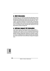
... display the menus. 30 ASRock 870iCafe Motherboard English Software Support CD information This motherboard supports various Microsoft® Windows® operating systems: 7 / 7 64-bit / VistaTM / VistaTM 64-bit / XP / XP 64-bit. To begin using the Support CD, insert the CD into your computer. If the Main Menu does not appear automatically, locate and doubleclick on the motherboard stores BIOS Setup Utility. When you start up the computer, please press during the Power...
... display the menus. 30 ASRock 870iCafe Motherboard English Software Support CD information This motherboard supports various Microsoft® Windows® operating systems: 7 / 7 64-bit / VistaTM / VistaTM 64-bit / XP / XP 64-bit. To begin using the Support CD, insert the CD into your computer. If the Main Menu does not appear automatically, locate and doubleclick on the motherboard stores BIOS Setup Utility. When you start up the computer, please press during the Power...
RAID Installation Guide
Page 4
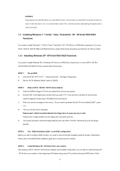
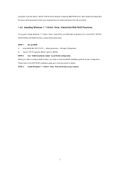
... system boot-up BIOS. STEP 1: Set up , press key, and then a window for proper configuration. B. STEP 3: Use "RAID Installation Guide" to set RAID configuration, you want to check this document for details. Then you will operate under a clean environment. 1.3 Installing Windows 7 / 7 64-bit / Vista / Vista 64-bit / XP / XP 64-bit With RAID Functions If you create RAID functions. Set the "SATA Operation Mode" option to "Clear Disk Data" or not. Insert the ASRock Support CD into the floppy drive...
... system boot-up BIOS. STEP 1: Set up , press key, and then a window for proper configuration. B. STEP 3: Use "RAID Installation Guide" to set RAID configuration, you want to check this document for details. Then you will operate under a clean environment. 1.3 Installing Windows 7 / 7 64-bit / Vista / Vista 64-bit / XP / XP 64-bit With RAID Functions If you create RAID functions. Set the "SATA Operation Mode" option to "Clear Disk Data" or not. Insert the ASRock Support CD into the floppy drive...
RAID Installation Guide
Page 5
... AMD RAID driver. Select your system. 5 A. Enter BIOS SETUP UTILITY → Advanced screen →Storage Configuration. STEP 2: Use "RAID Installation Guide" to [RAID]. STEP 3: Install Windows 7 / 7 64-bit / Vista / Vista 64-bit OS on your required driver to install according to the OS you install. 1.3.2 Installing Windows 7 / 7 64-bit / Vista / Vista 64-bit With RAID Functions If you need to the BIOS RAID installation guide part in this RAID installation guide for details. STEP 1: Set up BIOS. Set the "SATA Operation Mode" option to set RAID configuration. Before you start...
... AMD RAID driver. Select your system. 5 A. Enter BIOS SETUP UTILITY → Advanced screen →Storage Configuration. STEP 2: Use "RAID Installation Guide" to [RAID]. STEP 3: Install Windows 7 / 7 64-bit / Vista / Vista 64-bit OS on your required driver to install according to the OS you install. 1.3.2 Installing Windows 7 / 7 64-bit / Vista / Vista 64-bit With RAID Functions If you need to the BIOS RAID installation guide part in this RAID installation guide for details. STEP 1: Set up BIOS. Set the "SATA Operation Mode" option to set RAID configuration. Before you start...
RAID Installation Guide
Page 10
... AMD SB850 SATA RAID Controller (the "Host PC"). 2. Its browser-based GUI provides email notification of all components in order to access RAIDXpert over the network. 2.3 Installing RAIDXpert Follow these steps to your CD-ROM drive. 3. Other brands of the browsers listed above browsers, install the browser first and make it the default browser. If you must use one of RAIDXpert Installation Software RAIDXpert installation software will install...
... AMD SB850 SATA RAID Controller (the "Host PC"). 2. Its browser-based GUI provides email notification of all components in order to access RAIDXpert over the network. 2.3 Installing RAIDXpert Follow these steps to your CD-ROM drive. 3. Other brands of the browsers listed above browsers, install the browser first and make it the default browser. If you must use one of RAIDXpert Installation Software RAIDXpert installation software will install...


