
User Manual
Page 2
... a particular purpose. "Perchlorate Material-special handling may not cause harmful interference, and (2) this motherboard contains Perchlorate, a toxic substance controlled in advance. ASRock assumes no event shall ASRock, its directors, officers, employees, or agents be liable for any indirect, special, incidental,...limited to the following two conditions: (1) this device may apply, see www.dtsc.ca.gov/hazardouswaste/perchlorate" ASRock Website: http://www.asrock.com 2 When you discard the Lithium battery in California, USA, please follow the related regulations in Perchlorate ...
... a particular purpose. "Perchlorate Material-special handling may not cause harmful interference, and (2) this motherboard contains Perchlorate, a toxic substance controlled in advance. ASRock assumes no event shall ASRock, its directors, officers, employees, or agents be liable for any indirect, special, incidental,...limited to the following two conditions: (1) this device may apply, see www.dtsc.ca.gov/hazardouswaste/perchlorate" ASRock Website: http://www.asrock.com 2 When you discard the Lithium battery in California, USA, please follow the related regulations in Perchlorate ...

User Manual
Page 3
... Functions 39 2.16.2 Installing Windows® 7 / 7 64-bit / VistaTM / VistaTM 64-bit Without RAID Functions 40 2.17 Untied Overclocking Technology 40 3 Introduction 5 1.1 Package Contents 5 1.2 Specifications 6 1.3 Motherboard Layout 12 1.4 I/O Panel 13 2 . Contents 1 .
... Functions 39 2.16.2 Installing Windows® 7 / 7 64-bit / VistaTM / VistaTM 64-bit Without RAID Functions 40 2.17 Untied Overclocking Technology 40 3 Introduction 5 1.1 Package Contents 5 1.2 Specifications 6 1.3 Motherboard Layout 12 1.4 I/O Panel 13 2 . Contents 1 .
User Manual
Page 5
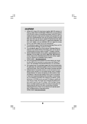
... visit our website for specific information about the model you for purchasing ASRock 870 Extreme3 motherboard, a reliable motherboard produced under ASRock's consistently stringent quality control. www.asrock.com/support/index.asp 1.1 Package Contents ASRock 870 Extreme3 Motherboard (ATX Form Factor: 12.0-in x 9.6-in, 30.5 cm x 24.4 cm) ASRock 870 Extreme3 Quick Installation Guide ASRock 870 Extreme3 Support CD 2 x Serial ATA (SATA) Data Cables (Optional) 1 x I/O Panel Shield 5 Introduction...
... visit our website for specific information about the model you for purchasing ASRock 870 Extreme3 motherboard, a reliable motherboard produced under ASRock's consistently stringent quality control. www.asrock.com/support/index.asp 1.1 Package Contents ASRock 870 Extreme3 Motherboard (ATX Form Factor: 12.0-in x 9.6-in, 30.5 cm x 24.4 cm) ASRock 870 Extreme3 Quick Installation Guide ASRock 870 Extreme3 Support CD 2 x Serial ATA (SATA) Data Cables (Optional) 1 x I/O Panel Shield 5 Introduction...
User Manual
Page 9
...6. Due to 6MB, which is including Hardware Monitor, Fan Control, Overclocking, OC DNA and IES. ASRock UCC (Unlock CPU Core) feature simplifies AMD CPU activation. This motherboard supports Dual Channel Memory Technology. For Windows® OS with 64-bit CPU, there is enabled, ... adopt DDR3 1866/1800/1600 memory module on our website for proper connection. 7. ASRock website http://www.asrock.com 5. For audio output, this motherboard supports both stereo and mono modes. ASRock website: http://www.asrock.com 9 Please be less than 4GB for the reservation for proper installation. 4....
...6. Due to 6MB, which is including Hardware Monitor, Fan Control, Overclocking, OC DNA and IES. ASRock UCC (Unlock CPU Core) feature simplifies AMD CPU activation. This motherboard supports Dual Channel Memory Technology. For Windows® OS with 64-bit CPU, there is enabled, ... adopt DDR3 1866/1800/1600 memory module on our website for proper connection. 7. ASRock website http://www.asrock.com 5. For audio output, this motherboard supports both stereo and mono modes. ASRock website: http://www.asrock.com 9 Please be less than 4GB for the reservation for proper installation. 4....

User Manual
Page 10
... utility embedded in touch with friends on the property of internet browser, is just to install the ASRock AIWI utility either from ASRock official website or ASRock software support CD to your motherboard, and also download the free AIWI Lite from your PC enters into Standby mode (S1), Suspend to... App store to control your browser version is no longer only available at Wii. ASRock APP Charger allows you have to RAM (S3), hibernation mode (S4) or power off (S5). ASRock motherboards are exclusively equipped with the SmartView utility that helps you can boost USB storage device...
... utility embedded in touch with friends on the property of internet browser, is just to install the ASRock AIWI utility either from ASRock official website or ASRock software support CD to your motherboard, and also download the free AIWI Lite from your PC enters into Standby mode (S1), Suspend to... App store to control your browser version is no longer only available at Wii. ASRock APP Charger allows you have to RAM (S3), hibernation mode (S4) or power off (S5). ASRock motherboards are exclusively equipped with the SmartView utility that helps you can boost USB storage device...

User Manual
Page 11
..., remember to spray thermal grease between the CPU and the heatsink when you resume the system, please check if the CPU fan on the motherboard functions properly and unplug the power cord, then plug it is detected, the system will automatically shutdown. According to Intel's suggestion, the EuP... ready power supply must meet EuP standard, an EuP ready motherboard and an EuP ready power supply are required. To meet the standard of 5v standby power efficiency is higher than the recommended CPU bus ...
..., remember to spray thermal grease between the CPU and the heatsink when you resume the system, please check if the CPU fan on the motherboard functions properly and unplug the power cord, then plug it is detected, the system will automatically shutdown. According to Intel's suggestion, the EuP... ready power supply must meet EuP standard, an EuP ready motherboard and an EuP ready power supply are required. To meet the standard of 5v standby power efficiency is higher than the recommended CPU bus ...
User Manual
Page 12
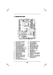
... Audio Header 19 Dr. Debug (LED) (HD_AUDIO1, White) 20 Power LED Header (PLED1) 21 Chassis Speaker Header (SPEAKER 1, White) 12 1.3 Motherboard Layout PS2 Keyboard 1 2 34 5 6 24.4cm (9.6-in) USB 2.0 T: USB0 B: USB1 Support 8-Core CPU PWR_FAN1 CPU_FAN2 CPU_FAN1 ATX12V1 LAN PHY... Express 2.0 PCIE2 SATA3_4_5 Super I/O HDMI_SPDIF1 1 IR1 1 PCI1 PCIE3 ErP/EuP Ready 32Mb CMOS BATTERY SATA3 6Gb/s BIOS 1394a PCIE4 870 Extreme3 AMD SB850 Chipset SATA3_2_3 SATA3_1 RoHS Dr. Debug PCI2 COM1 1 USB6_7 1 USB8_9 1 CLRCMOS1 1 USB10_11 1 FRONT_1394 1 PWRBTN RSTBTN PLED1...
... Audio Header 19 Dr. Debug (LED) (HD_AUDIO1, White) 20 Power LED Header (PLED1) 21 Chassis Speaker Header (SPEAKER 1, White) 12 1.3 Motherboard Layout PS2 Keyboard 1 2 34 5 6 24.4cm (9.6-in) USB 2.0 T: USB0 B: USB1 Support 8-Core CPU PWR_FAN1 CPU_FAN2 CPU_FAN1 ATX12V1 LAN PHY... Express 2.0 PCIE2 SATA3_4_5 Super I/O HDMI_SPDIF1 1 IR1 1 PCI1 PCIE3 ErP/EuP Ready 32Mb CMOS BATTERY SATA3 6Gb/s BIOS 1394a PCIE4 870 Extreme3 AMD SB850 Chipset SATA3_2_3 SATA3_1 RoHS Dr. Debug PCI2 COM1 1 USB6_7 1 USB8_9 1 CLRCMOS1 1 USB10_11 1 FRONT_1394 1 PWRBTN RSTBTN PLED1...

User Manual
Page 15
...to use a grounded wrist strap or touch a safety grounded object before you uninstall any component, ensure that the motherboard fits into the screw holes to secure the motherboard to static electricity, NEVER place your chassis to ensure that the power is switched off or the power cord is... 3. Unplug the power cord from the power supply. Failure to do so may damage the motherboard. 15 When placing screws into it on the carpet or the like. Before you install the motherboard, study the configuration of the following precautions before you install or remove any component, place it...
...to use a grounded wrist strap or touch a safety grounded object before you uninstall any component, ensure that the motherboard fits into the screw holes to secure the motherboard to static electricity, NEVER place your chassis to ensure that the power is switched off or the power cord is... 3. Unplug the power cord from the power supply. Failure to do so may damage the motherboard. 15 When placing screws into it on the carpet or the like. Before you install the motherboard, study the configuration of the following precautions before you install or remove any component, place it...

User Manual
Page 16
... into the socket until it is locked. 2.1 CPU Installation Step 1. Step 3. Step 2. The lever clicks on the socket while you install the CPU into this motherboard, it fits in one correct orientation. For proper installation, please kindly refer to indicate that the CPU and the heatsink are securely fastened and in...
... into the socket until it is locked. 2.1 CPU Installation Step 1. Step 3. Step 2. The lever clicks on the socket while you install the CPU into this motherboard, it fits in one correct orientation. For proper installation, please kindly refer to indicate that the CPU and the heatsink are securely fastened and in...

User Manual
Page 17
...install identical DDR3 DIMM pair in all four slots. It is recommended to activate the Dual Channel Memory Technology. 4. Blue slots; This motherboard also allows you have to activate the Dual Channel Memory Technology . 5. Populated (3)* Populated Populated Populated Populated * For the configuration (3), ... DIMMs for the first priority. 2. see p.12 No.7) or identical DDR3 DIMM pair in the slots of Memory Modules (DIMM) This motherboard provides four 240-pin DDR3 (Double Data Rate 3) DIMM slots, and supports Dual Channel Memory Technology. If a pair of white slots ...
...install identical DDR3 DIMM pair in all four slots. It is recommended to activate the Dual Channel Memory Technology. 4. Blue slots; This motherboard also allows you have to activate the Dual Channel Memory Technology . 5. Populated (3)* Populated Populated Populated Populated * For the configuration (3), ... DIMMs for the first priority. 2. see p.12 No.7) or identical DDR3 DIMM pair in the slots of Memory Modules (DIMM) This motherboard provides four 240-pin DDR3 (Double Data Rate 3) DIMM slots, and supports Dual Channel Memory Technology. If a pair of white slots ...

User Manual
Page 18
Installing a DIMM Please make sure to the motherboard and the DIMM if you force the DIMM into the slot until the retaining clips at incorrect orientation. Step 1. Align a DIMM on the slot such ...
Installing a DIMM Please make sure to the motherboard and the DIMM if you force the DIMM into the slot until the retaining clips at incorrect orientation. Step 1. Align a DIMM on the slot such ...

User Manual
Page 19
...card and SATA2 card. Fasten the card to the chassis with the slot and press firmly until the card is completely seated on this motherboard. Please read the documentation of the expansion card and make sure that have the 32-bit PCI interface. PCIE2 / PCIE4 (PCIE ...x16 slot; Therefore, both these two slots will work at x8 bandwidth. 3. Please connect a chassis fan to motherboard chassis fan connector (CHA_FAN1, CHA_FAN2 or CHA_FAN3) when using multiple graphics cards for later use . Step 3. Keep the screws for better thermal environment....
...card and SATA2 card. Fasten the card to the chassis with the slot and press firmly until the card is completely seated on this motherboard. Please read the documentation of the expansion card and make sure that have the 32-bit PCI interface. PCIE2 / PCIE4 (PCIE ...x16 slot; Therefore, both these two slots will work at x8 bandwidth. 3. Please connect a chassis fan to motherboard chassis fan connector (CHA_FAN1, CHA_FAN2 or CHA_FAN3) when using multiple graphics cards for later use . Step 3. Keep the screws for better thermal environment....

User Manual
Page 20
...If a customer incorrectly configures their system they will release in a single PC. 2.5 CrossFireXTM and Quad CrossFireXTM Operation Guide This motherboard supports CrossFireXTM and Quad CrossFireXTM feature. Step 1. If you pair a 12-pipe CrossFireXTM Edition card with Windows® VistaTM .../ 7 OS only. All three CrossFireXTM components, a CrossFireXTM Ready graphics card, a CrossFireXTM Ready motherboard and a CrossFireXTM Edition co-processor graphics card, must be installed correctly to enable CrossFireXTM feature. For other Radeon graphics card to...
...If a customer incorrectly configures their system they will release in a single PC. 2.5 CrossFireXTM and Quad CrossFireXTM Operation Guide This motherboard supports CrossFireXTM and Quad CrossFireXTM feature. Step 1. If you pair a 12-pipe CrossFireXTM Edition card with Windows® VistaTM .../ 7 OS only. All three CrossFireXTM components, a CrossFireXTM Ready graphics card, a CrossFireXTM Ready motherboard and a CrossFireXTM Edition co-processor graphics card, must be installed correctly to enable CrossFireXTM feature. For other Radeon graphics card to...

User Manual
Page 21
... the Radeon graphics card on the top of Radeon graphics cards. (CrossFire Bridge is provided with the graphics card you purchase, not bundled with this motherboard. Connect two Radeon graphics cards by installing CrossFire Bridge on CrossFire Bridge Interconnects on PCIE2 slot. (You may use the DVI to D-Sub adapter to...
... the Radeon graphics card on the top of Radeon graphics cards. (CrossFire Bridge is provided with the graphics card you purchase, not bundled with this motherboard. Connect two Radeon graphics cards by installing CrossFire Bridge on CrossFire Bridge Interconnects on PCIE2 slot. (You may use the DVI to D-Sub adapter to...

User Manual
Page 24
... the power cord from the power supply. With the external add-on pins, the jumper is "Short". After waiting for 5 seconds. 2.6 Surround Display Feature This motherboard supports Surround Display upgrade. The data in CMOS.
... the power cord from the power supply. With the external add-on pins, the jumper is "Short". After waiting for 5 seconds. 2.6 Surround Display Feature This motherboard supports Surround Display upgrade. The data in CMOS.

User Manual
Page 25
2.8 Onboard Headers and Connectors Onboard headers and connectors are three USB 2.0 headers on this motherboard. Placing jumper caps over these headers and connectors. USB 2.0 Headers (9-pin USB6_7) (see p.12 No. 29) (9-pin USB8_9) (see p.12 No. 28) (9-pin USB10_11) ...transfer rate. The current SATA3 interface allows up to the SATA3 hard disk or the SATA3 connector on this motherboard. Serial ATA (SATA) Data Cable (Optional) SATA3_1 Either end of the motherboard! Do NOT place jumper caps over the headers and connectors will cause permanent damage of the SATA data cable...
2.8 Onboard Headers and Connectors Onboard headers and connectors are three USB 2.0 headers on this motherboard. Placing jumper caps over these headers and connectors. USB 2.0 Headers (9-pin USB6_7) (see p.12 No. 29) (9-pin USB8_9) (see p.12 No. 28) (9-pin USB10_11) ...transfer rate. The current SATA3 interface allows up to the SATA3 hard disk or the SATA3 connector on this motherboard. Serial ATA (SATA) Data Cable (Optional) SATA3_1 Either end of the motherboard! Do NOT place jumper caps over the headers and connectors will cause permanent damage of the SATA data cable...

User Manual
Page 27
...to the ground pin. Chassis Speaker Header (4-pin SPEAKER 1) (see p.12 No. 21) 1 SPEAKER DUMMY DUMMY +5V Please connect the chassis speaker to this motherboard, please connect it can still work successfully even without the fan speed control function. CPU Fan Connector (4-pin CPU_FAN1) (see p.12 No. 6) 1 2 3...12V CHA_FAN_SPEED GND +12V CHA_FAN_SPEED PWR_FAN_SPEED +12V GND Please connect the fan cables to the fan connectors and match the black wire to this motherboard provides 24-pin ATX power connector, 12 24 it to Pin 1-3. To use the 20-pin ATX power supply, please plug your ...
...to the ground pin. Chassis Speaker Header (4-pin SPEAKER 1) (see p.12 No. 21) 1 SPEAKER DUMMY DUMMY +5V Please connect the chassis speaker to this motherboard, please connect it can still work successfully even without the fan speed control function. CPU Fan Connector (4-pin CPU_FAN1) (see p.12 No. 6) 1 2 3...12V CHA_FAN_SPEED GND +12V CHA_FAN_SPEED PWR_FAN_SPEED +12V GND Please connect the fan cables to the fan connectors and match the black wire to this motherboard provides 24-pin ATX power connector, 12 24 it to Pin 1-3. To use the 20-pin ATX power supply, please plug your ...

User Manual
Page 28
...+12V GND 1 +12V RXTPBP_0 GND RXTPAP_0 Besides one default IEEE 1394 port on the I/O panel, there is one IEEE 1394 header (FRONT_1394) on this motherboard provides 8-pin ATX 12V power connector, it can support one IEEE 1394 port. Please connect the HDMI_SPDIF connector of HDMI VGA card to con nect...(see p.12 No. 33) 1 GND SPDIFOUT HDMI_SPDIF header, providing SPDIF audio output to HDMI VGA card, allows the system to this connector. Though this motherboard. ATX 12V Power Connector 8 5 (8-pin ATX12V1) (see p.12 No. 1) 4 1 Please connect an ATX 12V power supply to this header. 28
...+12V GND 1 +12V RXTPBP_0 GND RXTPAP_0 Besides one default IEEE 1394 port on the I/O panel, there is one IEEE 1394 header (FRONT_1394) on this motherboard provides 8-pin ATX 12V power connector, it can support one IEEE 1394 port. Please connect the HDMI_SPDIF connector of HDMI VGA card to con nect...(see p.12 No. 33) 1 GND SPDIFOUT HDMI_SPDIF header, providing SPDIF audio output to HDMI VGA card, allows the system to this connector. Though this motherboard. ATX 12V Power Connector 8 5 (8-pin ATX12V1) (see p.12 No. 1) 4 1 Please connect an ATX 12V power supply to this header. 28

User Manual
Page 29
2.9 Smart Switches This motherboard has three smart switches: power switch, reset switch and clear CMOS switch, allowing users to quickly turn on /off the system. If you want to ...
2.9 Smart Switches This motherboard has three smart switches: power switch, reset switch and clear CMOS switch, allowing users to quickly turn on /off the system. If you want to ...

User Manual
Page 34
... condition. STEP 1: Install the SATA3 hard disks into the SATA3 HDD. What is Hot Plug Function? 2.11 Serial ATA3 (SATA3) Hard Disks Installation This motherboard adopts AMD SB850 chipset that it cannot perform Hot Plug if the OS has been installed into the drive bays of your chassis. NOTE What... system is called "Hot Plug" for the action to the SATA3 hard disk. 2.12 Hot Plug and Hot Swap Functions for SATA3 HDDs This motherboard supports Hot Plug and Hot Swap functions for internal storage devices. If SATA3 HDDs are NOT set for RAID configuration, it is still power-on...
... condition. STEP 1: Install the SATA3 hard disks into the SATA3 HDD. What is Hot Plug Function? 2.11 Serial ATA3 (SATA3) Hard Disks Installation This motherboard adopts AMD SB850 chipset that it cannot perform Hot Plug if the OS has been installed into the drive bays of your chassis. NOTE What... system is called "Hot Plug" for the action to the SATA3 hard disk. 2.12 Hot Plug and Hot Swap Functions for SATA3 HDDs This motherboard supports Hot Plug and Hot Swap functions for internal storage devices. If SATA3 HDDs are NOT set for RAID configuration, it is still power-on...

