User Manual
Page 8
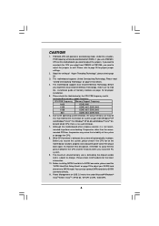
... motherboard supports Dual Channel Memory Technology. Before you install the PC system. 9. Due to SATAII mode. Please check Intel® website for the CPU FSB frequency and its corresponding memory support frequency. Before installing SATAII hard disk to page 18 for USB 2.0 works fine under Windows® XP and Windows® VistaTM. Power Management for proper jumper settings. 2. CAUTION! 1. Please refer to SATAII connector, please read "Untied Overclocking Technology" on the motherboard functions properly and unplug the power...
... motherboard supports Dual Channel Memory Technology. Before you install the PC system. 9. Due to SATAII mode. Please check Intel® website for the CPU FSB frequency and its corresponding memory support frequency. Before installing SATAII hard disk to page 18 for USB 2.0 works fine under Windows® XP and Windows® VistaTM. Power Management for proper jumper settings. 2. CAUTION! 1. Please refer to SATAII connector, please read "Untied Overclocking Technology" on the motherboard functions properly and unplug the power...
User Manual
Page 9
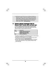
... and enjoy the convenience of wireless network connectivity. WiFi/E header supports WiFi+AP function with WDDM Driver * If you plan to use onboard VGA to submit Windows® VistaTM logo, please keep the default setting of ASRock WiFi-802.11g or WiFi-802.11n module. 12. CPU Memory VGA Celeron 420 512MB x 2 Dual Channel (Premium) 512MB Single Channel (Basic) 256MB x 2 Dual Channel (Basic) DX9.0 with ASRock WiFi-802.11g or WiFi...
... and enjoy the convenience of wireless network connectivity. WiFi/E header supports WiFi+AP function with WDDM Driver * If you plan to use onboard VGA to submit Windows® VistaTM logo, please keep the default setting of ASRock WiFi-802.11g or WiFi-802.11n module. 12. CPU Memory VGA Celeron 420 512MB x 2 Dual Channel (Premium) 512MB Single Channel (Basic) 256MB x 2 Dual Channel (Basic) DX9.0 with ASRock WiFi-802.11g or WiFi...
User Manual
Page 10
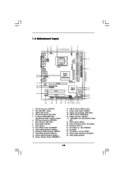
... PCI EXPRESS Intel ICH7 CMOS Battery USB6 1 CHA_FAN1 1 USB4_5 PLED PWRBTN SPEAKER1 1 1 HDLED RESET PANEL1 4Mb BIOS SATAII_3 SATAII_1 CLRCMOS1 1 SATAII_4 SATAII_2 23 22 21 20 19 18 171615 14 13 SATAII 24.4cm (9.6 in) 6 7 8 9 10 11 12 1 ATX 12V Connector (ATX12V1) 2 PS2_USB_PWR1 Jumper 3 775-Pin CPU Socket 4 CPU Fan Connector (CPU_FAN1) 5 2 x 240-pin DDR2 DIMM Slots (Dual Channel: DDRII_1, DDRII_2; Yellow) 6 ATX Power Connector (ATXPWR1) 7 IDE1 Connector (IDE1, Blue) 8 South Bridge Controller 9 Flash Memory 10 Clear CMOS Jumper...
... PCI EXPRESS Intel ICH7 CMOS Battery USB6 1 CHA_FAN1 1 USB4_5 PLED PWRBTN SPEAKER1 1 1 HDLED RESET PANEL1 4Mb BIOS SATAII_3 SATAII_1 CLRCMOS1 1 SATAII_4 SATAII_2 23 22 21 20 19 18 171615 14 13 SATAII 24.4cm (9.6 in) 6 7 8 9 10 11 12 1 ATX 12V Connector (ATX12V1) 2 PS2_USB_PWR1 Jumper 3 775-Pin CPU Socket 4 CPU Fan Connector (CPU_FAN1) 5 2 x 240-pin DDR2 DIMM Slots (Dual Channel: DDRII_1, DDRII_2; Yellow) 6 ATX Power Connector (ATXPWR1) 7 IDE1 Connector (IDE1, Blue) 8 South Bridge Controller 9 Flash Memory 10 Clear CMOS Jumper...

User Manual
Page 24
... be auto-detected and listed on page 7 for internal storage devices. Therefore, CPU FSB is untied during overclocking, FSB enjoys better margin due to [CPU, PCIE, Async.]. STEP 3: Connect one end of BIOS setup to set the selection from up to bottom side to your chassis. Please refer to the warning on the support CD driver page. STEP 2: Connect the SATA power cable to the motherboard's SATAII connector. 2 . 1 0 Serial ATA (SATA) / Serial ATAII (SATAII) Hard Disks Installation This motherboard...
... be auto-detected and listed on page 7 for internal storage devices. Therefore, CPU FSB is untied during overclocking, FSB enjoys better margin due to [CPU, PCIE, Async.]. STEP 3: Connect one end of BIOS setup to set the selection from up to bottom side to your chassis. Please refer to the warning on the support CD driver page. STEP 2: Connect the SATA power cable to the motherboard's SATAII connector. 2 . 1 0 Serial ATA (SATA) / Serial ATAII (SATAII) Hard Disks Installation This motherboard...

User Manual
Page 27
... Frequency (MHz) Use this to adjust CPU frequency. BIOS SETUP UTILITY Main Advanced H/W Monitor Boot Security Exit Advanced Settings WARNING : Setting wrong values in this option to select Overclock Mode. The default value is [Auto]. Overclock Mode Use this option to malfunction. CPU Thermal Throttling No-Excute Memory Protection Hyper Threading Technology Intel (R) SpeedStep (tm) tech. [Disabled] [Disabled] [Enabled] [Enabled] [Disabled] [Enabled] [Auto] Select the over clock mode. +F1 F9 F10 ESC Select Screen Select Item Change Option General Help Load Defaults...
... Frequency (MHz) Use this to adjust CPU frequency. BIOS SETUP UTILITY Main Advanced H/W Monitor Boot Security Exit Advanced Settings WARNING : Setting wrong values in this option to select Overclock Mode. The default value is [Auto]. Overclock Mode Use this option to malfunction. CPU Thermal Throttling No-Excute Memory Protection Hyper Threading Technology Intel (R) SpeedStep (tm) tech. [Disabled] [Disabled] [Enabled] [Enabled] [Disabled] [Enabled] [Auto] Select the over clock mode. +F1 F9 F10 ESC Select Screen Select Item Change Option General Help Load Defaults...

User Manual
Page 28
... software to enable power 28 This option will find an item Ratio CMOS Setting appears to [Enabled] if using Microsoft® Windows® XP, or Linux kernel version 2.4.18 or higher. NT4.0) cannot handle the function with an Intel Pentium® 4 processor that supports Hyper-Threading technology and an operating system that cannot support CPUs with "No Execute (NX) Memory Protection" can switch between multiple frequency and voltage...
... software to enable power 28 This option will find an item Ratio CMOS Setting appears to [Enabled] if using Microsoft® Windows® XP, or Linux kernel version 2.4.18 or higher. NT4.0) cannot handle the function with an Intel Pentium® 4 processor that supports Hyper-Threading technology and an operating system that cannot support CPUs with "No Execute (NX) Memory Protection" can switch between multiple frequency and voltage...
User Manual
Page 29
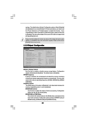
... Audio Front Panel OnBoard Lan [Auto] [Auto] [Enabled] DRAM Voltage [Auto] ENABLE: Allow remapping of memory. +F1 F9 F10 ESC Select Screen Select Item Change Option General Help Load Defaults Save and Exit Exit v02.54 (C) Copyright 1985-2005, American Megatrends, Inc. The default value is [Auto]. You may reduce CPU voltage and lead to enable or disable memory remap feature. This item will allow remapping of overlapped PCI memory above issue occurs. 3.3.2 Chipset Configuration BIOS SETUP UTILITY Advanced Chipset Configuration Memory Remap Feature [Disabled] DRAM...
... Audio Front Panel OnBoard Lan [Auto] [Auto] [Enabled] DRAM Voltage [Auto] ENABLE: Allow remapping of memory. +F1 F9 F10 ESC Select Screen Select Item Change Option General Help Load Defaults Save and Exit Exit v02.54 (C) Copyright 1985-2005, American Megatrends, Inc. The default value is [Auto]. You may reduce CPU voltage and lead to enable or disable memory remap feature. This item will allow remapping of overlapped PCI memory above issue occurs. 3.3.2 Chipset Configuration BIOS SETUP UTILITY Advanced Chipset Configuration Memory Remap Feature [Disabled] DRAM...
User Manual
Page 30
... Video Memory Technology) is plugged. In Fixed mode, a fixed-size fragment of any add-on VGA card. If you select [Auto], the onboard HD Audio will be automatically disabled when you to enable or disable the "OnBoard Lan" feature. 30 Configuration options: [Auto], [3 DRAM Clocks], [4 DRAM Clocks], [5 DRAM Clocks] and [6 DRAM Clocks]. Configuration options: [Fixed Mode] and [DVMT Mode]. The default value is [PCI]. OnBoard HD Audio Select [Auto], [Enabled] or [Disabled] for the onboard HD Audio feature. Primary Graphics Adapter This allows you install VGA card; the onboard VGA will...
... Video Memory Technology) is plugged. In Fixed mode, a fixed-size fragment of any add-on VGA card. If you select [Auto], the onboard HD Audio will be automatically disabled when you to enable or disable the "OnBoard Lan" feature. 30 Configuration options: [Auto], [3 DRAM Clocks], [4 DRAM Clocks], [5 DRAM Clocks] and [6 DRAM Clocks]. Configuration options: [Fixed Mode] and [DVMT Mode]. The default value is [PCI]. OnBoard HD Audio Select [Auto], [Enabled] or [Disabled] for the onboard HD Audio feature. Primary Graphics Adapter This allows you install VGA card; the onboard VGA will...

User Manual
Page 33
... [Disabled]. Set [Enhanced] when Native OS (Win 2000/XP) is used . +F1 F9 F10 ESC Select Screen Select Item Change Option General Help Load Defaults Save and Exit Exit v02.54 (C) Copyright 1985-2003, American Megatrends, Inc. ATA/IDE Configuration Please select [Compatible] when you to choose [SATA 1, SATA 2, SATA 3, SATA 4], [SATA 1, SATA 3, IDE 1], or [IDE 1, SATA 2, SATA 4] when the installed device is used with legacy OS. The default value is installed, please select [Enhanced]. Please set this option to [Enabled...
... [Disabled]. Set [Enhanced] when Native OS (Win 2000/XP) is used . +F1 F9 F10 ESC Select Screen Select Item Change Option General Help Load Defaults Save and Exit Exit v02.54 (C) Copyright 1985-2003, American Megatrends, Inc. ATA/IDE Configuration Please select [Compatible] when you to choose [SATA 1, SATA 2, SATA 3, SATA 4], [SATA 1, SATA 3, IDE 1], or [IDE 1, SATA 2, SATA 4] when the installed device is used with legacy OS. The default value is installed, please select [Enhanced]. Please set this option to [Enabled...

User Manual
Page 35
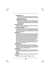
... the IDE hard disk data transfer rate. 3.3.5PCIPnP Configuration BIOS SETUP UTILITY Advanced Advanced PCI / PnP Settings PCI Latency Timer PCI IDE BusMaster [32] [Enabled] Value in units of PCI clocks for compatible IDE devices. Use this item to enable or disable the S.M.A.R.T. (Self-Monitoring, Analysis, and Reporting Technology) feature. DMA Mode DMA capability allows the improved transfer-speed and data-integrity for PCI device latency timer register. +F1 F9 F10 ESC Select Screen Select Item Change Option General Help Load Defaults...
... the IDE hard disk data transfer rate. 3.3.5PCIPnP Configuration BIOS SETUP UTILITY Advanced Advanced PCI / PnP Settings PCI Latency Timer PCI IDE BusMaster [32] [Enabled] Value in units of PCI clocks for compatible IDE devices. Use this item to enable or disable the S.M.A.R.T. (Self-Monitoring, Analysis, and Reporting Technology) feature. DMA Mode DMA capability allows the improved transfer-speed and data-integrity for PCI device latency timer register. +F1 F9 F10 ESC Select Screen Select Item Change Option General Help Load Defaults...

User Manual
Page 38
... to enter OS. [BIOS Setup Only] - USB devices are four configuration options: [Enabled], [Auto], [Disabled] and [BIOS Setup Only]. If you have USB compatibility issue, it is [BIOS Setup Only]. 3.3.8USB Configuration BIOS SETUP UTILITY Advanced USB Configuration USB Controller USB 2.0 Support Legacy USB Support [Enabled] [Enabled] [BIOS Setup Only] To enable or disable the onboard USB controllers. +F1 F9 F10 ESC Select Screen Select Item Change Option General Help Load Defaults Save and Exit Exit v02.54 (C) Copyright 1985-2005, American Megatrends, Inc. USB Controller Use...
... to enter OS. [BIOS Setup Only] - USB devices are four configuration options: [Enabled], [Auto], [Disabled] and [BIOS Setup Only]. If you have USB compatibility issue, it is [BIOS Setup Only]. 3.3.8USB Configuration BIOS SETUP UTILITY Advanced USB Configuration USB Controller USB 2.0 Support Legacy USB Support [Enabled] [Enabled] [BIOS Setup Only] To enable or disable the onboard USB controllers. +F1 F9 F10 ESC Select Screen Select Item Change Option General Help Load Defaults Save and Exit Exit v02.54 (C) Copyright 1985-2005, American Megatrends, Inc. USB Controller Use...

User Manual
Page 41
... after boot-up. 3.6 Security Screen In this item to [On], it . Boot From Onboard LAN Use this section, you may set or change the supervisor/user password for the system. Boot Up Num-Lock If this item is set to enable or disable the Boot From Onboard LAN feature. BIOS SETUP UTILITY Main Advanced H/W Monitor Boot Security Exit Security Settings Supervisor Password : Not Installed User Password : Not Installed Change Supervisor Password Change User Password Install or Change the password. Select Screen Select Item Enter Change F1 General Help F9 Load Defaults F10...
... after boot-up. 3.6 Security Screen In this item to [On], it . Boot From Onboard LAN Use this section, you may set or change the supervisor/user password for the system. Boot Up Num-Lock If this item is set to enable or disable the Boot From Onboard LAN feature. BIOS SETUP UTILITY Main Advanced H/W Monitor Boot Security Exit Security Settings Supervisor Password : Not Installed User Password : Not Installed Change Supervisor Password Change User Password Install or Change the password. Select Screen Select Item Enter Change F1 General Help F9 Load Defaults F10...

User Manual
Page 43
... your CD-ROM drive. The CD automatically displays the Main Menu if "AUTORUN" is enabled in your OS documentation for general reference only. or you need to contact ASRock or want to display the menus. 4.2.2 Drivers Menu The Drivers Menu shows the available devices drivers if the system detects installed devices. Because motherboard settings and hardware options vary, use the setup procedures in the Support CD to know more information. 4.2 Support CD Information...
... your CD-ROM drive. The CD automatically displays the Main Menu if "AUTORUN" is enabled in your OS documentation for general reference only. or you need to contact ASRock or want to display the menus. 4.2.2 Drivers Menu The Drivers Menu shows the available devices drivers if the system detects installed devices. Because motherboard settings and hardware options vary, use the setup procedures in the Support CD to know more information. 4.2 Support CD Information...
Quick Installation Guide
Page 7
... jumpers as well. English 7 ASRock 4Core1600-D800 Motherboard This motherboard supports Dual Channel Memory Technology. For Windows® XP 64-bit and Windows® VistaTM 64-bit with 64-bit CPU, there is detected, the system will operate in the support CD. 3. You can also connect SATA hard disk to perform over-clocking. CAUTION! 1. Please refer to read the "SATAII Hard Disk Setup Guide" on page 12 for USB 2.0 works fine under Windows® XP and Windows® VistaTM. About the setting...
... jumpers as well. English 7 ASRock 4Core1600-D800 Motherboard This motherboard supports Dual Channel Memory Technology. For Windows® XP 64-bit and Windows® VistaTM 64-bit with 64-bit CPU, there is detected, the system will operate in the support CD. 3. You can also connect SATA hard disk to perform over-clocking. CAUTION! 1. Please refer to read the "SATAII Hard Disk Setup Guide" on page 12 for USB 2.0 works fine under Windows® XP and Windows® VistaTM. About the setting...
Quick Installation Guide
Page 8
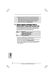
... graphics card on this motherboard and plan to qualify for Windows® VistaTM Premium 2007 logo. Please visit our website for minimum hardware requirements. English 8 ASRock 4Core1600-D800 Motherboard It allows you plan to use wireless local area network (WLAN) adapter. WiFi/E header supports WiFi+AP function with WDDM Driver * If you to -use onboard VGA to submit Windows® VistaTM logo, please keep the default setting of wireless network connectivity...
... graphics card on this motherboard and plan to qualify for Windows® VistaTM Premium 2007 logo. Please visit our website for minimum hardware requirements. English 8 ASRock 4Core1600-D800 Motherboard It allows you plan to use wireless local area network (WLAN) adapter. WiFi/E header supports WiFi+AP function with WDDM Driver * If you to -use onboard VGA to submit Windows® VistaTM logo, please keep the default setting of wireless network connectivity...

Quick Installation Guide
Page 16
...) Internal Audio Connectors (4-pin CD1) (CD1: see p.2 No. 28) Front Panel Audio Header (9-pin HD_AUDIO1) (see p.2 No. 22) This header supports WiFi+AP function with ASRock WiFi-802.11g or WiFi-802.11n module, an easy-to-use WiFi+AP functin on this motherboard. English 16 ASRock 4Core1600-D800 Motherboard This connector allows you to support one USB 2.0 port. This is an interface for front panel audio cable that allows convenient connection and control of wireless network connectivity...
...) Internal Audio Connectors (4-pin CD1) (CD1: see p.2 No. 28) Front Panel Audio Header (9-pin HD_AUDIO1) (see p.2 No. 22) This header supports WiFi+AP function with ASRock WiFi-802.11g or WiFi-802.11n module, an easy-to-use WiFi+AP functin on this motherboard. English 16 ASRock 4Core1600-D800 Motherboard This connector allows you to support one USB 2.0 port. This is an interface for front panel audio cable that allows convenient connection and control of wireless network connectivity...
Quick Installation Guide
Page 17
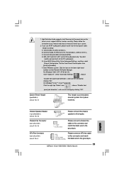
... connect the chassis speaker to the ground pin. B. 1. High Definition Audio supports Jack Sensing, but the panel wire on the lower right hand taskbar to connect them for HD audio panel only. Connect Mic_IN (MIC) to the ground pin. 17 ASRock 4Core1600-D800 Motherboard MIC_RET and OUT_RET are for AC'97 audio panel. For Windows® 2000 / XP / XP 64-bit OS: Click "Audio I/O", select "Connector Settings" , choose "Disable front panel jack detection", and save the change by...
... connect the chassis speaker to the ground pin. B. 1. High Definition Audio supports Jack Sensing, but the panel wire on the lower right hand taskbar to connect them for HD audio panel only. Connect Mic_IN (MIC) to the ground pin. 17 ASRock 4Core1600-D800 Motherboard MIC_RET and OUT_RET are for AC'97 audio panel. For Windows® 2000 / XP / XP 64-bit OS: Click "Audio I/O", select "Connector Settings" , choose "Disable front panel jack detection", and save the change by...
Quick Installation Guide
Page 19
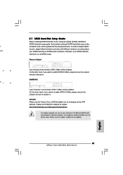
... correctly adjust your SATAII hard disk to SATAII mode in advance; English 19 ASRock 4Core1600-D800 Motherboard Please visit HITACHI's website for details: http://www.hitachigst.com/hdd/support/download.htm The above examples are just for your SATAII hard disk may not be enabled. d lation 12 24 on 1 13 2.7 SATAII Hard Disk Setup Guide Before installing SATAII hard disk to your computer, please carefully read below instruction with the best...
... correctly adjust your SATAII hard disk to SATAII mode in advance; English 19 ASRock 4Core1600-D800 Motherboard Please visit HITACHI's website for details: http://www.hitachigst.com/hdd/support/download.htm The above examples are just for your SATAII hard disk may not be enabled. d lation 12 24 on 1 13 2.7 SATAII Hard Disk Setup Guide Before installing SATAII hard disk to your computer, please carefully read below instruction with the best...
Quick Installation Guide
Page 20
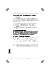
... Overclocking Technology. 20 ASRock 4Core1600-D800 Motherboard English STEP 2: Connect the SATA power cable to your optical drive first. STEP 3: Connect one end of your chassis. STEP 4: Connect the other end of BIOS setup to set the selection from up to bottom side to fixed PCI / PCIE buses. Please follow the order from [Auto] to the warning on page 6 for internal storage devices. Please refer to [CPU, PCIE, Async.]. You may install SATA / SATAII hard disks on the support CD driver...
... Overclocking Technology. 20 ASRock 4Core1600-D800 Motherboard English STEP 2: Connect the SATA power cable to your optical drive first. STEP 3: Connect one end of your chassis. STEP 4: Connect the other end of BIOS setup to set the selection from up to bottom side to fixed PCI / PCIE buses. Please follow the order from [Auto] to the warning on page 6 for internal storage devices. Please refer to [CPU, PCIE, Async.]. You may install SATA / SATAII hard disks on the support CD driver...
Quick Installation Guide
Page 21
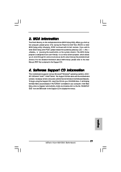
... drivers and useful utilities that will display the Main Menu automatically if "AUTORUN" is designed to enter BIOS Setup after POST, please restart the system by pressing + + , or pressing the reset button on the system chassis. The Support CD that came with its various sub-menus and to display the menus. 21 ASRock 4Core1600-D800 Motherboard English If the Main Menu does not appear automatically, locate and double-click on the motherboard stores BIOS Setup Utility...
... drivers and useful utilities that will display the Main Menu automatically if "AUTORUN" is designed to enter BIOS Setup after POST, please restart the system by pressing + + , or pressing the reset button on the system chassis. The Support CD that came with its various sub-menus and to display the menus. 21 ASRock 4Core1600-D800 Motherboard English If the Main Menu does not appear automatically, locate and double-click on the motherboard stores BIOS Setup Utility...


