
Operating Instructions
Page 4
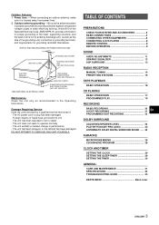
... YOUR SYSTEM AND ACCESSORIES 4 BASIC CONNECTIONS 4 CONNECTING OTHER EQUIPMENTS 6 CONNECTING A DVD PLAYER 8 REMOTE CONTROL 9 BEFORE OPERATION 9 SOUND AUDIO ADJUSTMENTS 11 GRAPHIC EQUALIZER 12 DSP SURROUND 13 RADIO RECEPTION MANUAL TUNING 14 PRESETTING STATIONS 15 TAPE PLAYBACK BASIC OPERATIONS 16 CD PLAYING BASIC ... 21 En PROGRAMMED EDIT RECORDING 22 DOLBY SURROUND ADJUSTING SPEAKER LEVEL 23 PLAY WITH DOLBY PRO LOGIC 24 LISTENING TO DOLBY DIGITAL SURROUND SOUND ...... 25 KARAOKE MICROPHONE MIXING 26 CD KARAOKE PROGRAM 28 CLOCK AND TIMER SETTING THE CLOCK 29 SETTING THE...
... YOUR SYSTEM AND ACCESSORIES 4 BASIC CONNECTIONS 4 CONNECTING OTHER EQUIPMENTS 6 CONNECTING A DVD PLAYER 8 REMOTE CONTROL 9 BEFORE OPERATION 9 SOUND AUDIO ADJUSTMENTS 11 GRAPHIC EQUALIZER 12 DSP SURROUND 13 RADIO RECEPTION MANUAL TUNING 14 PRESETTING STATIONS 15 TAPE PLAYBACK BASIC OPERATIONS 16 CD PLAYING BASIC ... 21 En PROGRAMMED EDIT RECORDING 22 DOLBY SURROUND ADJUSTING SPEAKER LEVEL 23 PLAY WITH DOLBY PRO LOGIC 24 LISTENING TO DOLBY DIGITAL SURROUND SOUND ...... 25 KARAOKE MICROPHONE MIXING 26 CD KARAOKE PROGRAM 28 CLOCK AND TIMER SETTING THE CLOCK 29 SETTING THE...
Operating Instructions
Page 7
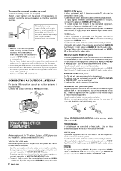
...the FM antenna near metal objects or curtain rails. • Do not bring the AM antenna near other accidents caused by the audio cable. 6 ENGLISH • When CD DIGITAL OUT (OPTICAL) jack is recommended. The signals input through VIDEO 1 IN jack are firmly secured. CONNECTING AN OUTDOOR ANTENNA For better... AM antenna wire. NOTE • Be sure to FM 75 Ω terminals. Connect the outdoor antenna to connect the speaker cords correctly. Aiwa disclaims any responsibility for injury to these jacks. NOTE The signals input through VIDEO 2 IN jack are output to this jack.
...the FM antenna near metal objects or curtain rails. • Do not bring the AM antenna near other accidents caused by the audio cable. 6 ENGLISH • When CD DIGITAL OUT (OPTICAL) jack is recommended. The signals input through VIDEO 1 IN jack are firmly secured. CONNECTING AN OUTDOOR ANTENNA For better... AM antenna wire. NOTE • Be sure to FM 75 Ω terminals. Connect the outdoor antenna to connect the speaker cords correctly. Aiwa disclaims any responsibility for injury to these jacks. NOTE The signals input through VIDEO 2 IN jack are output to this jack.

Operating Instructions
Page 8
...Video out jack to Audio in jacks and Video in jack to Audio out jacks and Video out jack to Audio in jacks and Video in jacks o CD-ROM driver, MD recorder, etc. Turntable to Digital in jack REC OUT/ VIDEO2/LD/TV VIDEO1/DVD/MD AUDIO MONITOR CX-A1000 (rear) MONITOR/ ...VIDEO2/LD/TV VIDEO1/DVD VIDEO OUT CD DIGITAL OUT (OPTICAL) PHONO IN AUX IN En TV to Video in jack o to Audio out jacks CX-A1000 (front) Camcorder to Audio in jack o o o o to Audio out jacks and Video out jack 7 ENGLISH o...
...Video out jack to Audio in jacks and Video in jack to Audio out jacks and Video out jack to Audio in jacks and Video in jacks o CD-ROM driver, MD recorder, etc. Turntable to Digital in jack REC OUT/ VIDEO2/LD/TV VIDEO1/DVD/MD AUDIO MONITOR CX-A1000 (rear) MONITOR/ ...VIDEO2/LD/TV VIDEO1/DVD VIDEO OUT CD DIGITAL OUT (OPTICAL) PHONO IN AUX IN En TV to Video in jack o to Audio out jacks CX-A1000 (front) Camcorder to Audio in jack o o o o to Audio out jacks and Video out jack 7 ENGLISH o...

Operating Instructions
Page 9
... equipment is not connected to AUX IN jacks: - the spectrum analyzer does not show the sound level of this unit support the DOLBY DIGITAL SURROUND system (see page 25). The signals through MONITOR/VIDEO OUT jack is not displayed. 2 Play the connected equipment. Refer also to.... CONNECTING A DVD PLAYER 5.1CH INPUT jacks of the sources depending on the equipment connected to the input terminals on the TV. SELECTING EXTERNAL AUDIO/VIDEO SOURCES AUX/PHONO/5.1CH VIDEO 1/2/3 f,g To play equipment connected to the unit, proceed as below. When VIDEO1/2/3 is pressed VIDEO1 VIDEO2 ...
... equipment is not connected to AUX IN jacks: - the spectrum analyzer does not show the sound level of this unit support the DOLBY DIGITAL SURROUND system (see page 25). The signals through MONITOR/VIDEO OUT jack is not displayed. 2 Play the connected equipment. Refer also to.... CONNECTING A DVD PLAYER 5.1CH INPUT jacks of the sources depending on the equipment connected to the input terminals on the TV. SELECTING EXTERNAL AUDIO/VIDEO SOURCES AUX/PHONO/5.1CH VIDEO 1/2/3 f,g To play equipment connected to the unit, proceed as below. When VIDEO1/2/3 is pressed VIDEO1 VIDEO2 ...
Operating Instructions
Page 12
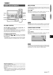
...En NOTE Low-frequency sound may be set to PHONES jack with BBE, it is output from 0 to avoid distorted high frequency sound. PREPASROAUTINDONS SOUND AUDIO ADJUSTMENTS T-BASS BBE PHONES VOLUME MANUAL SELECT T-BASS VOL / BBE SYSTEM The BBE system enhances the clarity of low-frequency sound. Each time it is... (page 25) do not function. Press f or g on the remote control within these 2 seconds. • The DOLBY PRO LOGIC (page 24) and the DOLBY DIGITAL SURROUND (page 25) front speakers level is used for 2 seconds. In this case, cancel the T-BASS system. ENGLISH 11
...En NOTE Low-frequency sound may be set to PHONES jack with BBE, it is output from 0 to avoid distorted high frequency sound. PREPASROAUTINDONS SOUND AUDIO ADJUSTMENTS T-BASS BBE PHONES VOLUME MANUAL SELECT T-BASS VOL / BBE SYSTEM The BBE system enhances the clarity of low-frequency sound. Each time it is... (page 25) do not function. Press f or g on the remote control within these 2 seconds. • The DOLBY PRO LOGIC (page 24) and the DOLBY DIGITAL SURROUND (page 25) front speakers level is used for 2 seconds. In this case, cancel the T-BASS system. ENGLISH 11

Operating Instructions
Page 33
SPECIFICATIONS Main unit CX-A1000 FM tuner section Tuning range 87.5 MHz to 108 MHz...THD less than 1 %, 8 ohms) 100 W (1 kHz, THD less than 10 %, 8 ohms) Total harmonic distortion 0.15 % (40 W, 1 kHz, 8 ohms, DIN AUDIO/Front) LOW FREQ + SUB WOOFER amplifier Power output 200 W + 200 W (50 Hz - 200 Hz, THD less than 1 %, 6 ohms) 250 W + 250 W ...300 mV SURROUND: 300 mV CENTER: 600 mV SUB WOOFER: 300 mV MIC 1, MIC 2: 1.4 mV (20 kohms) Outputs CD DIGITAL OUT (OPTICAL) SPEAKERS: LOW + SUB WOOFER 6 ohms HIGH 8 ohms SURROUND SPEAKERS: accept speakers of 8 -16 ohms CENTER SPEAKER:...
SPECIFICATIONS Main unit CX-A1000 FM tuner section Tuning range 87.5 MHz to 108 MHz...THD less than 1 %, 8 ohms) 100 W (1 kHz, THD less than 10 %, 8 ohms) Total harmonic distortion 0.15 % (40 W, 1 kHz, 8 ohms, DIN AUDIO/Front) LOW FREQ + SUB WOOFER amplifier Power output 200 W + 200 W (50 Hz - 200 Hz, THD less than 1 %, 6 ohms) 250 W + 250 W ...300 mV SURROUND: 300 mV CENTER: 600 mV SUB WOOFER: 300 mV MIC 1, MIC 2: 1.4 mV (20 kohms) Outputs CD DIGITAL OUT (OPTICAL) SPEAKERS: LOW + SUB WOOFER 6 ohms HIGH 8 ohms SURROUND SPEAKERS: accept speakers of 8 -16 ohms CENTER SPEAKER:...


