AIWA NSX-A505 Support and Manuals
Get Help and Manuals for this AIWA item

View All Support Options Below
Free AIWA NSX-A505 manuals!
Problems with AIWA NSX-A505?
Ask a Question
Free AIWA NSX-A505 manuals!
Problems with AIWA NSX-A505?
Ask a Question
Popular AIWA NSX-A505 Manual Pages
Service Manual - Page 1

...
REMOTE CONTROLLER
0
NSX-A505
CX-NA505 (TYPE : U)
SX-NA502
NSX-S505
CX-NS505 (TYPE : LH)
SX-NS503
RC - 7AS06
NSX-5507
CX-N5507 (TYPE : LH)
SX-FNS705
• If requiring information about the CD mechanism, see Service Manual of 4ZG-1, S/M Code No. 09-983-249-3OT. • This Service Manual is the "Revision Publishing" and replaces "Simple Manual", S/M Code No. 09-983...
Service Manual - Page 2

TABLE OF CONTENTS
SPECIFICATIONS NOTE ON BEFORE STARTING REPAIR PROTECTION OF EYES FROM LASER BEAM DURING SERVICING PRECAUTION TO REPLACE OPTICAL BLOCK ELECTRICAL MAIN PARTS LIST TRANSISTOR ILLUSTRATION FL GRID ASSIGNMENT & ANODE CONNECTION IC BLOCK DIAGRAM -1 BLOCK DIAGRAM (MAIN / FRONT) WIRING -1 (MAIN) SCHEMATIC DIAGRAM -1 (MAIN 112) SCHEMATIC DIAGRAM - 2 (FRONT) WIRING - 2 (...
Service Manual - Page 3

SPECIFICATIONS
Service Manual - Page 4

...
PIN number is "L", the main power cannot be turned on the models, Be sure to check the following table. Discharge procedure
® ...25.48 49-140
Discharging resistor (1-2)
100 220
Rated power (W) 3 5
Parts number 87-A00-247-090 87-A00-232-090
Fig-1
Note: The ...block
When repair is going to be attempted in the set that sets the HOLD terminal to prevent the secondary trouble, perform the...
Service Manual - Page 5

... leads to wrong judgment as if the MICROCOMPUTER is defective and to exchange the MICROCOMPU1ER after surely confirming that the trouble is good. Be sure to check the reference numbers on the models. Be sure to exchange the MICROCOMPUTER. If the MICROCOMPUTER returns to the above described phenomenon occurs, it can change...
Service Manual - Page 6
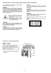
...SERVICING
This set employs laser.
II Acivarseg: Usynlig laserstatIng ved alining,
nar sikkerhedsafbrydere er ude at funktion.
This Compact...LASER APPARAT
Precaution to follow carefully the instructions below when servicing. Undgt udsmttelse for straling.
Undga udsmttelse...UP Assy P.C.B Solder
-6- Therefore, be sure to replace Optical block
(KSS - 213F)
Body or clothes ...
Service Manual - Page 19

A , i
5305 EFFECT
LED43o
it II
I
L 4:-• -
::- ii ., ,.,.1 r..)
,.;11-r`
4 ,..,.-4_1„-I
210.,.9119.9a_
•
)) ,•1 \ :'1 7--1-. -1,
. J-12I- D ''''
.
F
VCL
5302 IENTEEL
5r3o0cd8
5307
/„..-7;„7/
NP 0 1
7
/ifir9'
L
Ili I
V IL 7 0;("!...,..-Ii___i-_s/-_.%-.rL_.7,_.I EECl/ALAI
E
rt.
11 -/
L H ONLY
- ,5- 3• 49•...
Service Manual - Page 27

...
MIX RF.A p
0 r-3 COMP
A
FM
METER
T1'
N IF
S-CURVE T
AI C
AM
f]ET}
AM S-MET R'
AM/FM IF-BUFF
A
TaURNCVE
sTana
DRIVE
2
1
26
SECOOER ANTI BIRtiE
PHASE SET
STEREO SW
la
17
364042 380
FF
FF --› ISIGZ0
ON
VC- IC, LC72131
XIN xOUT
FM4 16
AMIN
CE 4
CL ( 00 6 VOF0 17 VSS
REFERENCE...
Service Manual - Page 28

...:
Less than 1.5%
[at 10001(fiz]
Auto stop level :
25dB ± 10dB [at 98.0MHz.]
Stereo separation :
More than 30dB [at 98.0MHz)
Intermediate frequency : I ? a 0 0
I 0.7MHz
Sensitivity...72dB
Stereo : More than 6640
[at 98.0MHz ]
Distortion
Mono : Less than 1.2%
Stereo : Less than 35dB
[at 87.5 / 98.0 I I LTER
GEO ILTER
V2
j. 5W4
!
C•R MIE IN
PRACTICAL SERVICE ...
Service Manual - Page 30

... data input.
Power supply input FL segment PI - DECK 2 solenoid output. Tuner stereo detected input / CD SQ CLOCK output. SURR input to diode. FL segment PI0 ... data input. CD clock output. VDD2
O-POWER
O
O-S-MUTE
O
SOL 1
O
SOL 2
O
O-MOTOR
O
1-1FC/STEREO/SUBQ 1
I -STEREO/ 1/O
DRF(SQCLK)
I-RDS-DATA/
I/O O-CDCE
RT-A
I
RT-B
I
Description FL segment P26 output / FM1 (...
Service Manual - Page 31

... check that the test point is less than 8.5V(1710kHz) and more than 0.5V.
- 39 - MW Tracking Adjustment
Settings : • Test point : TP8(Lch), TP9(Rch) • Adjustment location :
L981(1/3)
1000kHz
Method : Set to AM 1000kHz and adjust L98I (1/3) to FM 87.5MHz and check that the test point is 2160kHz ±...
Service Manual - Page 32

...Method : Play back the test tape and adjust SFRI so that the output becomes maximum. Head Azimuth Adjustment Settings • Test tape : TTA-330 • Test point : TP6(Lch), TP7(Rch) • ...test tape and adjust screw so that the frequency counter reads 3000Hz t 5Hz. REC/PB Frequency Response Adjustment Settings : • Test tape TTA-602 • Test point : TP6(Lch), TP7(Rch) • ...
Service Manual - Page 41
...019 13 82-ZM1-207-619 14 86-U4-206-010 15 82-Z1C-314-119
CEAR,H T SPR-T,HEAD GUIDE,TAPE S-SCREW,AzniUTH PLATE, HEAD
16 82-D41-206-119 17 B2-2(1-218-019 18 82-2N1-263-110 18...N2
D 87-810-043-010 W-P,0.99-4-0.25 SLT B 82-2143-334-010 PN,2.16-6-0.4
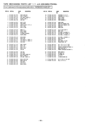
- 50 - TAPE MECHANISM PARTS LIST 1 /1
If can't understand for Description please kindly refer to " REFERENCE NAME LIST ".
REF.
KMRI NO. NC...
Service Manual - Page 44

...-NS7-606-010 3 87-1W-610-010 4 87-ES7-611-0]0 S 87-NSE-612-010
BADGE,AIWA 35 SPXR W140 SPICA T60 CORB,SPXR SPNR,CERAMIC ASSY
6 88-NS.7-001-00 PANEL,FR
SX-NS503 (YLSTNCC) SPEAKER PARTS LIST
If can 't understand for Description please kindly refer to " REFERENCE NAME LIST ". SX-NA502...
Service Manual - Page 45

...RESONATOR, CRYSTAL
VR ZENER
VOLUME DIODE, ZENER
1*
itleP§IN
G-
-.1-vnitrais4±
AIWA CO.,LTD.
1110-8710
MECHANICAL SECTION
DESCRIPTION
REFERENCE NAME
ADHESHIVE AZ BAR-ANT BAT BATT
SHEET...BAT
FUNCTION G-CUSHION HANDOL CLOTH HINGE, BATTERY
HLDR HT-SINK IS IDLE IND, L-R
HOLDER HEAT SINK INSTRUCTION BOOKLET IDLER INDICATOR, L-R
KEY, CONT KEY, P RGM KNOB, SL LBL LID, BATT
KEY, ...
AIWA NSX-A505 Reviews
We have not received any reviews for AIWA yet.