Getting Started Guide
Page 3
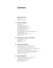
... Introduction 7 Switch 4800G 24-Port 8 Switch 4800G PWR 48-Port 11 Switch 4800G PWR 24-Port 13 Switch 4800G 24-Port SFP 17 Switch 4800G 48-Port 18 System Specifications of the Switch 4800G Series 22 Pluggable Modules 22 Optional Interface Modules 23 CX4 Cable 24 2 PREPARATING TO INSTALL THE SWITCH Safety Precautions ...the Switch on a Workbench 38 Connecting the Power Cables and the Grounding Cable 38 Connecting the Console Cable 46 Installing and Removing Optional Interface Modules 47 Installing and Removing the Dedicated CX4 Cable 50 Verifying the Installation 51 4 INITIAL POWER-ON Setting ...
... Introduction 7 Switch 4800G 24-Port 8 Switch 4800G PWR 48-Port 11 Switch 4800G PWR 24-Port 13 Switch 4800G 24-Port SFP 17 Switch 4800G 48-Port 18 System Specifications of the Switch 4800G Series 22 Pluggable Modules 22 Optional Interface Modules 23 CX4 Cable 24 2 PREPARATING TO INSTALL THE SWITCH Safety Precautions ...the Switch on a Workbench 38 Connecting the Power Cables and the Grounding Cable 38 Connecting the Console Cable 46 Installing and Removing Optional Interface Modules 47 Installing and Removing the Dedicated CX4 Cable 50 Verifying the Installation 51 4 INITIAL POWER-ON Setting ...
Getting Started Guide
Page 53
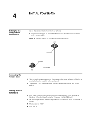
...54 Network diagram for configuration environment setup Switch Console port Serial port Connecting the Console Cable Setting Terminal Parameters Console cable PC 1 Plug the DB-9 female connector of the console cable to the serial port of the PC or terminal where the switch is to be configured. 2 Connect... per second: 9,600 4 Data bits: 8 4 INITIAL POWER-ON Setting Up the Configuration Environment Set up the configuration environment as follows: ■ Connect a terminal (a PC in this example) to the console port of the switch. 1 Start the PC and run the terminal emulation program such as...
...54 Network diagram for configuration environment setup Switch Console port Serial port Connecting the Console Cable Setting Terminal Parameters Console cable PC 1 Plug the DB-9 female connector of the console cable to the serial port of the PC or terminal where the switch is to be configured. 2 Connect... per second: 9,600 4 Data bits: 8 4 INITIAL POWER-ON Setting Up the Configuration Environment Set up the configuration environment as follows: ■ Connect a terminal (a PC in this example) to the console port of the switch. 1 Start the PC and run the terminal emulation program such as...
Getting Started Guide
Page 57
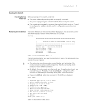
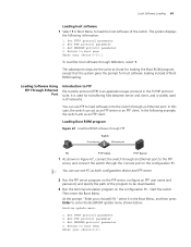
... takes a little longer time than the fast startup mode because of Switch 4800G 48-Port as an example: Starting...... * * * 3Com Switch 4800G 48-Port BOOTROM, Version 205 * * * Copyright(c) 2004-2008 3Com Corporation. For the setting of the startup mode, refer to the next section. ■ If...Booting the Switch 57 Booting the Switch Checking before Power-On Before powering on the switch, verify that: ■ The power cable and grounding cable are properly connected. ■ The power supply voltage is consistent with that required by the switch. ■ The console cable is...
... takes a little longer time than the fast startup mode because of Switch 4800G 48-Port as an example: Starting...... * * * 3Com Switch 4800G 48-Port BOOTROM, Version 205 * * * Copyright(c) 2004-2008 3Com Corporation. For the setting of the startup mode, refer to the next section. ■ If...Booting the Switch 57 Booting the Switch Checking before Power-On Before powering on the switch, verify that: ■ The power cable and grounding cable are properly connected. ■ The power supply voltage is consistent with that required by the switch. ■ The console cable is...
Getting Started Guide
Page 62
... your choice(0-9):" select 6 in flash 4. XModem transfers files via Console port. Loading BootROM software 1 At the prompt "Enter your choice(0-9): Loading Software Using XModem Through the Console Port Introduction to its simplicity and good performance. 62 CHAPTER 5: ...of a receiving program and a sending program. appears. Set bootrom password recovery 9. Set TFTP protocol parameter otherwise, the receiving program sends a negative acknowledgement packet and the sending program retransmits the packet. Set switch startup mode 0. After the negotiation, the sending program...
... your choice(0-9):" select 6 in flash 4. XModem transfers files via Console port. Loading BootROM software 1 At the prompt "Enter your choice(0-9): Loading Software Using XModem Through the Console Port Introduction to its simplicity and good performance. 62 CHAPTER 5: ...of a receiving program and a sending program. appears. Set bootrom password recovery 9. Set TFTP protocol parameter otherwise, the receiving program sends a negative acknowledgement packet and the sending program retransmits the packet. Set switch startup mode 0. After the negotiation, the sending program...

Getting Started Guide
Page 63
The system displays the following information: Download baudrate is chosen, and the system displays the following download baud rate setting menu: Please select your choice(0-3): 2 Select 3 in the above menu to boot menu Enter your download baudrate: 1.* 9600 2. 19200 3. 38400 4. 57600 5. 115200...bps and select XMODE M protocol Press enter key when ready Press Enter after the information above information. 4 Select File > Properties in the console port configuration dialog box. in the popup dialog box, select the bits per second of 115,200 in HyperTerminal, click Configure... In this ...
The system displays the following information: Download baudrate is chosen, and the system displays the following download baud rate setting menu: Please select your choice(0-3): 2 Select 3 in the above menu to boot menu Enter your download baudrate: 1.* 9600 2. 19200 3. 38400 4. 57600 5. 115200...bps and select XMODE M protocol Press enter key when ready Press Enter after the information above information. 4 Select File > Properties in the console port configuration dialog box. in the popup dialog box, select the bits per second of 115,200 in HyperTerminal, click Configure... In this ...

Getting Started Guide
Page 65
Click the Disconnect icon to disconnect the HyperTerminal and then the Call icon to reconnect the HyperTerminal to disconnect and the reconnect HyperTerminal so that the baud rate setting can take effect. Figure 62 Disconnect the HyperTerminal Figure 61 Console port configuration dialog box Local Software Loading 65 5 After setting the baud rate, you need to the switch.
Click the Disconnect icon to disconnect the HyperTerminal and then the Call icon to reconnect the HyperTerminal to disconnect and the reconnect HyperTerminal so that the baud rate setting can take effect. Figure 62 Disconnect the HyperTerminal Figure 61 Console port configuration dialog box Local Software Loading 65 5 After setting the baud rate, you need to the switch.
Getting Started Guide
Page 68
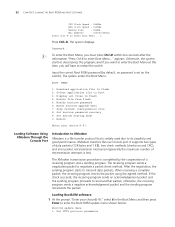
... update menu. n You can use one PC as required: Load File name Switch IP address Server IP address :Switch 4800G.btm :1.1.1.2 :1.1.1.1 5 Press Enter after entering the information above. Set XMODEM protocol parameter 0. Then set the following TFTP-related parameters as both configuration device and TFTP server. 2 Run...for trivial file transfer between client and server. Loading Boot ROM program Figure 66 Load the Boot ROM program through TFTP Switch Console port Ethernet port PC TFTP Client TFTP Server 1 As shown in TCP/IP protocol suite, is completed: Loading done Bootrom ...
... update menu. n You can use one PC as required: Load File name Switch IP address Server IP address :Switch 4800G.btm :1.1.1.2 :1.1.1.1 5 Press Enter after entering the information above. Set XMODEM protocol parameter 0. Then set the following TFTP-related parameters as both configuration device and TFTP server. 2 Run...for trivial file transfer between client and server. Loading Boot ROM program Figure 66 Load the Boot ROM program through TFTP Switch Console port Ethernet port PC TFTP Client TFTP Server 1 As shown in TCP/IP protocol suite, is completed: Loading done Bootrom ...
Getting Started Guide
Page 69
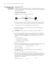
... ROM program Figure 67 Load BootROM software through FTP Switch Console port Ethernet port PC FTP Client FTP Server 1 As shown in Figure 67, connect the switch through an Ethernet port to the FTP server, and connect the switch through XModem, select 1. Local Software Loading 69 Loading... protocol suite. Start the switch. The system displays the following example, the switch acts as an FTP server or an FTP client. Set XMODEM protocol parameter 0. Return to boot menu Enter your choice(0-3):1 To load the host software through the Console port to be downloaded....
... ROM program Figure 67 Load BootROM software through FTP Switch Console port Ethernet port PC FTP Client FTP Server 1 As shown in Figure 67, connect the switch through an Ethernet port to the FTP server, and connect the switch through XModem, select 1. Local Software Loading 69 Loading... protocol suite. Start the switch. The system displays the following example, the switch acts as an FTP server or an FTP client. Set XMODEM protocol parameter 0. Return to boot menu Enter your choice(0-3):1 To load the host software through the Console port to be downloaded....
Getting Started Guide
Page 74
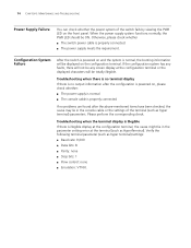
...has any faults, there will not be any screen display at the configuration terminal, the cause might lie in the console cable or the settings of the switch fails by viewing the PWR LED on and the system is properly connected. ■ The power supply meets the ...). Verify the following terminal parameter (such as hyper terminal) settings: ■ Baud rate: 9,600 ■ Data bits: 8 ■ Parity: none ■ Stop bits: 1 ■ Flow control: none ■ Emulation: VT100. Configuration System Failure After the switch is powered on the front panel. 74 CHAPTER 6: MAINTENANCE AND...
...has any faults, there will not be any screen display at the configuration terminal, the cause might lie in the console cable or the settings of the switch fails by viewing the PWR LED on and the system is properly connected. ■ The power supply meets the ...). Verify the following terminal parameter (such as hyper terminal) settings: ■ Baud rate: 9,600 ■ Data bits: 8 ■ Parity: none ■ Stop bits: 1 ■ Flow control: none ■ Emulation: VT100. Configuration System Failure After the switch is powered on the front panel. 74 CHAPTER 6: MAINTENANCE AND...


