Getting Started Guide
Page 3
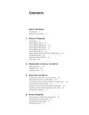
... GUIDE Conventions 5 Related Documentation 5 1 PRODUCT OVERVIEW Introduction 7 Switch 4800G 24-Port 8 Switch 4800G PWR 48-Port 11 Switch 4800G PWR 24-Port 13 Switch 4800G 24-Port SFP 17 Switch 4800G 48-Port 18 System Specifications of the Switch 4800G Series 22 Pluggable Modules 22 Optional Interface Modules 23 CX4 Cable 24 2 PREPARATING TO INSTALL THE SWITCH Safety Precautions 25 Installation Site 25 Installation Tools...
... GUIDE Conventions 5 Related Documentation 5 1 PRODUCT OVERVIEW Introduction 7 Switch 4800G 24-Port 8 Switch 4800G PWR 48-Port 11 Switch 4800G PWR 24-Port 13 Switch 4800G 24-Port SFP 17 Switch 4800G 48-Port 18 System Specifications of the Switch 4800G Series 22 Pluggable Modules 22 Optional Interface Modules 23 CX4 Cable 24 2 PREPARATING TO INSTALL THE SWITCH Safety Precautions 25 Installation Site 25 Installation Tools...
Getting Started Guide
Page 7
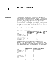
... networks (MANs). Table 2 Models of the Switch 4800G Model Switch 4800G 24-Port Switch 4800G PWR 48-Port Switch 4800G PWR 24-Port Switch 4800G 24-Port SFP Switch 4800G 48-Port Number of auto-sensing 10/100/1000Base-T Ethernet ports 24 48 24 48 8 Number of Number of the Switch 4800G. 1 PRODUCT OVERVIEW Introduction 3Com Switch 4800G Family (hereinafter referred to as 3Com). Table 2 lists the models of 1000Base...
... networks (MANs). Table 2 Models of the Switch 4800G Model Switch 4800G 24-Port Switch 4800G PWR 48-Port Switch 4800G PWR 24-Port Switch 4800G 24-Port SFP Switch 4800G 48-Port Number of auto-sensing 10/100/1000Base-T Ethernet ports 24 48 24 48 8 Number of Number of the Switch 4800G. 1 PRODUCT OVERVIEW Introduction 3Com Switch 4800G Family (hereinafter referred to as 3Com). Table 2 lists the models of 1000Base...
Getting Started Guide
Page 9
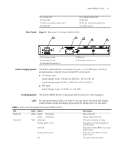
...mode between speed and duplex by pressing the Mode button on the front panel of the Switch 4800G 24-Port LED Mode LED Power LED Mark Status Mode Speed Solid green Duplex Solid yellow PWR Solid green Flashing green (1 Hz) Solid red Flashing yellow (1 Hz) OFF Description ...Rate of the port Duplex mode of the Switch 4800G 24-Port (1) (2) (3) (4) (5) (1) AC power socket (3) Grounding screw (5) Extended module slot 2 ...
...mode between speed and duplex by pressing the Mode button on the front panel of the Switch 4800G 24-Port LED Mode LED Power LED Mark Status Mode Speed Solid green Duplex Solid yellow PWR Solid green Flashing green (1 Hz) Solid red Flashing yellow (1 Hz) OFF Description ...Rate of the port Duplex mode of the Switch 4800G 24-Port (1) (2) (3) (4) (5) (1) AC power socket (3) Grounding screw (5) Extended module slot 2 ...
Getting Started Guide
Page 11
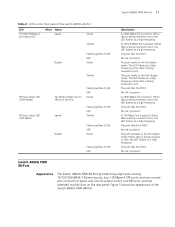
...sent The port fails the POST. A 100 Mbps link is present. No link is present. Figure 5 shows the appearance of the Switch 4800G 24-Port LED 10/100/1000Base-T port status LED Mark Status - The port fails the POST. The port operates in the full...1000 Mbps link is being received or sent, the LED flashes at a high frequency. Switch 4800G PWR 48-Port 11 Table 4 LEDs on the front panel of the Switch 4800G PWR 48-Port. Switch 4800G PWR 48-Port Appearance The Switch 4800G PWR 48-Port provides forty-eight auto-sensing 10/100/1000BASE-T Ethernet ports, four 1000Base-X...
...sent The port fails the POST. A 100 Mbps link is present. No link is present. Figure 5 shows the appearance of the Switch 4800G 24-Port LED 10/100/1000Base-T port status LED Mark Status - The port fails the POST. The port operates in the full...1000 Mbps link is being received or sent, the LED flashes at a high frequency. Switch 4800G PWR 48-Port 11 Table 4 LEDs on the front panel of the Switch 4800G PWR 48-Port. Switch 4800G PWR 48-Port Appearance The Switch 4800G PWR 48-Port provides forty-eight auto-sensing 10/100/1000BASE-T Ethernet ports, four 1000Base-X...
Getting Started Guide
Page 12
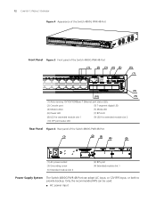
...can adopt AC input, or 12V RPS input, or both to provide backup. 12 CHAPTER 1: PRODUCT OVERVIEW Figure 4 Appearance of the Switch 4800G PWR 48-Port Front Panel Figure 5 Front panel of the Switch 4800G PWR 48-Port (1) (2) (3) (4) (5) (6) (7) (8 ) (10) (9) (1) Auto-sensing 10/100/1000Base-T Ethernet port status LEDs... LED for extended module slot 2 (10) SFP port status LED Rear Panel Figure 6 Rear panel of the Switch 4800G PWR 48-Port (1) (2) (3) (4) (5) (1) AC power socket (3) Grounding screw (5) Extended module slot 2 (2) RPS port (4) Extended module slot 1 Power Supply System...
...can adopt AC input, or 12V RPS input, or both to provide backup. 12 CHAPTER 1: PRODUCT OVERVIEW Figure 4 Appearance of the Switch 4800G PWR 48-Port Front Panel Figure 5 Front panel of the Switch 4800G PWR 48-Port (1) (2) (3) (4) (5) (6) (7) (8 ) (10) (9) (1) Auto-sensing 10/100/1000Base-T Ethernet port status LEDs... LED for extended module slot 2 (10) SFP port status LED Rear Panel Figure 6 Rear panel of the Switch 4800G PWR 48-Port (1) (2) (3) (4) (5) (1) AC power socket (3) Grounding screw (5) Extended module slot 2 (2) RPS port (4) Extended module slot 1 Power Supply System...
Getting Started Guide
Page 13
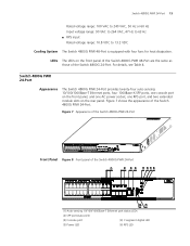
...status LEDs (2) SFP port status LED (3) Console port (4) 7-segment digital LED (5) Power LED (6) RPS LED For details, see Table 4. Switch 4800G PWR 24-Port Appearance The Switch 4800G PWR 24-Port provides twenty-four auto-sensing 10/100/1000Base-T Ethernet ports, four 1000Base-X SFP ports, one console port on the front panel...one AC power socket, one RPS port, and two extended module slots on the front panel of the Switch 4800G PWR 48-Port are the same as those of the Switch 4800G 24-Port. Switch 4800G PWR 24-Port 13 Rated voltage range: 100 VAC to 240 VAC, 50 Hz or 60 Hz Input ...
...status LEDs (2) SFP port status LED (3) Console port (4) 7-segment digital LED (5) Power LED (6) RPS LED For details, see Table 4. Switch 4800G PWR 24-Port Appearance The Switch 4800G PWR 24-Port provides twenty-four auto-sensing 10/100/1000Base-T Ethernet ports, four 1000Base-X SFP ports, one console port on the front panel...one AC power socket, one RPS port, and two extended module slots on the front panel of the Switch 4800G PWR 48-Port are the same as those of the Switch 4800G 24-Port. Switch 4800G PWR 24-Port 13 Rated voltage range: 100 VAC to 240 VAC, 50 Hz or 60 Hz Input ...
Getting Started Guide
Page 14
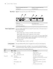
... VAC to 240 VAC, 50 Hz or 60 Hz Rated voltage range: 90 VAC to 264 VAC, 47 Hz to -55 VDC Cooling System The Switch 4800G PWR 24-Port is equipped with six fans for heat dissipation. The power is disconnected. The system is running a power-on the panel. You can be... damaged. ■ DC power input Rated voltage range: -52 VDC to 63 Hz Only the RPS recommended by 3Com can switch the Mode LED display mode between speed, duplex, and PoE by pressing the Mode button on self-test (POST). 14 CHAPTER 1: PRODUCT OVERVIEW (7) LED...
... VAC to 240 VAC, 50 Hz or 60 Hz Rated voltage range: 90 VAC to 264 VAC, 47 Hz to -55 VDC Cooling System The Switch 4800G PWR 24-Port is equipped with six fans for heat dissipation. The power is disconnected. The system is running a power-on the panel. You can be... damaged. ■ DC power input Rated voltage range: -52 VDC to 63 Hz Only the RPS recommended by 3Com can switch the Mode LED display mode between speed, duplex, and PoE by pressing the Mode button on self-test (POST). 14 CHAPTER 1: PRODUCT OVERVIEW (7) LED...
Getting Started Guide
Page 15
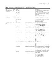
..., but an AC power failure occurs or no AC power is only one unit. Fan failure The power LED is in position and works normally. Switch 4800G PWR 24-Port 15 Table 5 Descriptions of the LEDs on the front panel of the power supply. 81 - 100% 61 - 80% 41 - 60% 21 - 40% 0 - 20...% The module is solid red. Over-temperature alarm The power LED is solid red. The LED displays the utilization of Switch 4800G PWR 24-Port LED Redundant power system LED Mark Status RPS Solid green Solid yellow Module LED OFF MOD Solid green Flashing yellow OFF 7-segment digital...
..., but an AC power failure occurs or no AC power is only one unit. Fan failure The power LED is in position and works normally. Switch 4800G PWR 24-Port 15 Table 5 Descriptions of the LEDs on the front panel of the power supply. 81 - 100% 61 - 80% 41 - 60% 21 - 40% 0 - 20...% The module is solid red. Over-temperature alarm The power LED is solid red. The LED displays the utilization of Switch 4800G PWR 24-Port LED Redundant power system LED Mark Status RPS Solid green Solid yellow Module LED OFF MOD Solid green Flashing yellow OFF 7-segment digital...
Getting Started Guide
Page 16
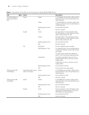
... fails the POST. The LED flashes at a high frequency. The port works in the full duplex mode. No link is present. The required power of Switch 4800G PWR 24-Port LED Mark Status 10/100/1000Base-T Ethernet port status LED Speed Duplex PoE Green Yellow Flashing yellow (3 Hz) OFF Green Yellow Flashing yellow...
... fails the POST. The LED flashes at a high frequency. The port works in the full duplex mode. No link is present. The required power of Switch 4800G PWR 24-Port LED Mark Status 10/100/1000Base-T Ethernet port status LED Speed Duplex PoE Green Yellow Flashing yellow (3 Hz) OFF Green Yellow Flashing yellow...
Getting Started Guide
Page 18
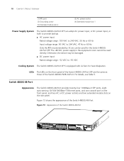
... VDC to 264 VAC, 47 Hz or 63 Hz Only the RPS recommended by 3Com can be used directly. For details, see Table 5. Figure 13 shows the appearance of the Switch 4800G 48-Port Figure 13 Appearance of the Switch 4800G 48-Port. Otherwise, the device may be used for heat dissipation. LEDs The LEDs... one console port on the front panel, and two AC or DC power sockets and two extended module slots on the front panel of the Switch 4800G 24-Port SFP are the same as those of the Switch 4800G PWR 24-Port.
... VDC to 264 VAC, 47 Hz or 63 Hz Only the RPS recommended by 3Com can be used directly. For details, see Table 5. Figure 13 shows the appearance of the Switch 4800G 48-Port Figure 13 Appearance of the Switch 4800G 48-Port. Otherwise, the device may be used for heat dissipation. LEDs The LEDs... one console port on the front panel, and two AC or DC power sockets and two extended module slots on the front panel of the Switch 4800G 24-Port SFP are the same as those of the Switch 4800G PWR 24-Port.
Getting Started Guide
Page 22
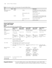
... Description A 100 Mbps link is present. 22 CHAPTER 1: PRODUCT OVERVIEW Table 6 Description of LEDs on the front panel of the Switch 4800G Item Switch 4800G 24-Port Switch 4800G PWR 48-Port Switch 4800G PWR 24-Port Switch 4800G 24-Port SFP Switch 4800G 48-Port Physical dimensions (H × W × D) 43.6 × 440 × 300 mm (1.72 × 17.3 × 11.8 in.) 43.6 ×...
... Description A 100 Mbps link is present. 22 CHAPTER 1: PRODUCT OVERVIEW Table 6 Description of LEDs on the front panel of the Switch 4800G Item Switch 4800G 24-Port Switch 4800G PWR 48-Port Switch 4800G PWR 24-Port Switch 4800G 24-Port SFP Switch 4800G 48-Port Physical dimensions (H × W × D) 43.6 × 440 × 300 mm (1.72 × 17.3 × 11.8 in.) 43.6 ×...
Getting Started Guide
Page 30
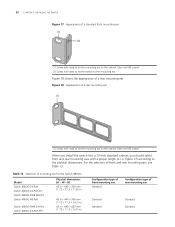
... Figure 18 shows the appearance of a rear mounting ear. Table 13 Selection of mounting ear for the Switch 4800G Model Switch 4800G 24-Port Switch 4800G 24-Port-DC Switch 4800G PWR 48-Port Switch 4800G 48-Port Switch 4800G PWR 24-Port Switch 4800G 24-Port SFP Physical dimensions (H × W × D) 43.6 × 440 × 300...× 420 mm (1.72 × 17.3 × 16.5 in Figure 17) according to the physical dimensions. 30 CHAPTER 3: INSTALLING THE SWITCH Figure 17 Appearance of a standard front mounting ear (1) (2) (1) Screw hole used to fix the mounting ear to the cabinet (Use one M6 ...
... Figure 18 shows the appearance of a rear mounting ear. Table 13 Selection of mounting ear for the Switch 4800G Model Switch 4800G 24-Port Switch 4800G 24-Port-DC Switch 4800G PWR 48-Port Switch 4800G 48-Port Switch 4800G PWR 24-Port Switch 4800G 24-Port SFP Physical dimensions (H × W × D) 43.6 × 440 × 300...× 420 mm (1.72 × 17.3 × 16.5 in Figure 17) according to the physical dimensions. 30 CHAPTER 3: INSTALLING THE SWITCH Figure 17 Appearance of a standard front mounting ear (1) (2) (1) Screw hole used to fix the mounting ear to the cabinet (Use one M6 ...
Getting Started Guide
Page 39
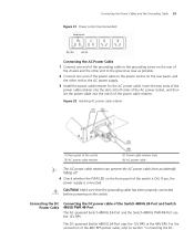
... accidentally falling off. 4 Check whether the PWR LED on the rear panel, and the other end to the ground as near as possible. 2 Connect one end of the power cable to the power socket on the front panel of the switch is connected. The DC-powered Switch 4800G 24-Port uses the 12V RPS... or the 48V RPS. If yes, the power supply is ON. For the connection of the Switch 4800G 24-Port and Switch 4800G PWR 48-Port The AC-powered Switch 4800G 24-Port and the Switch 4800G PWR 48-Port use the 12V RPS. Connecting the DC Power Cable Connecting the DC power cable of the 48V...
... accidentally falling off. 4 Check whether the PWR LED on the rear panel, and the other end to the ground as near as possible. 2 Connect one end of the power cable to the power socket on the front panel of the switch is connected. The DC-powered Switch 4800G 24-Port uses the 12V RPS... or the 48V RPS. If yes, the power supply is ON. For the connection of the Switch 4800G 24-Port and Switch 4800G PWR 48-Port The AC-powered Switch 4800G 24-Port and the Switch 4800G PWR 48-Port use the 12V RPS. Connecting the DC Power Cable Connecting the DC power cable of the 48V...

Getting Started Guide
Page 40
... cable of the grounding cable to the ground as near as follows: 1 Connect one end of the Switch 4800G 48-Port and Switch 4800G 24-Port-DC" on the rear panel and the other end to the grounding screw on page 43. Figure 34 12V RPS power cable Figure ... 12V GND Pin Number 8 9 10 11 12 13 14 Designation GND -50V RPS_pres -50Vrtn -50Vrtn Control Pin GND Connect the DC power cable of the Switch 4800G 24-Port and Switch 4800G PWR 48-Port as possible. 2 Connect the 12V RPS power connectors.
... cable of the grounding cable to the ground as near as follows: 1 Connect one end of the Switch 4800G 48-Port and Switch 4800G 24-Port-DC" on the rear panel and the other end to the grounding screw on page 43. Figure 34 12V RPS power cable Figure ... 12V GND Pin Number 8 9 10 11 12 13 14 Designation GND -50V RPS_pres -50Vrtn -50Vrtn Control Pin GND Connect the DC power cable of the Switch 4800G 24-Port and Switch 4800G PWR 48-Port as possible. 2 Connect the 12V RPS power connectors.
Getting Started Guide
Page 42
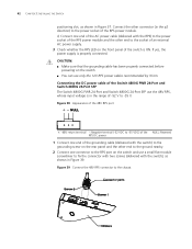
... Figure 39 Connect the 48V RPS connector to the power socket of the Switch 4800G PWR 24-Port and Switch 4800G 24-Port SFP The Switch 4800G PWR 24-Port and Switch 4800G 24-Port SFP use only the 12V RPS power cables recommended by 3Com. If yes, the power supply is ON. 42 CHAPTER 3: INSTALLING THE... SWITCH positioning slot, as shown in Figure 39. c CAUTION: ■ Make sure that...
... Figure 39 Connect the 48V RPS connector to the power socket of the Switch 4800G PWR 24-Port and Switch 4800G 24-Port SFP The Switch 4800G PWR 24-Port and Switch 4800G 24-Port SFP use only the 12V RPS power cables recommended by 3Com. If yes, the power supply is ON. 42 CHAPTER 3: INSTALLING THE... SWITCH positioning slot, as shown in Figure 39. c CAUTION: ■ Make sure that...
Getting Started Guide
Page 74
... illegible. Otherwise, please check whether ■ The switch power cable is normal, the booting information will be any screen display at the terminal (such as HyperTerminal). When the power supply system functions normally, the PWR LED should be displayed on the configuration terminal. Troubleshooting...cable is illegible display at the configuration terminal, the cause might lie in the console cable or the settings of the switch fails by viewing the PWR LED on and the system is properly connected. ■ The power supply meets the requirement. 74 CHAPTER 6: MAINTENANCE...
... illegible. Otherwise, please check whether ■ The switch power cable is normal, the booting information will be any screen display at the terminal (such as HyperTerminal). When the power supply system functions normally, the PWR LED should be displayed on the configuration terminal. Troubleshooting...cable is illegible display at the configuration terminal, the cause might lie in the console cable or the settings of the switch fails by viewing the PWR LED on and the system is properly connected. ■ The power supply meets the requirement. 74 CHAPTER 6: MAINTENANCE...

