Getting Started Guide
Page 3
... Interface Modules 23 CX4 Cable 24 2 PREPARATING TO INSTALL THE SWITCH Safety Precautions 25 Installation Site 25 Installation Tools 27 3 INSTALLING THE SWITCH Installing the Switch into a 19-Inch Cabinet 29 Mounting the Switch on a Workbench 38 Connecting the Power Cables and the Grounding Cable 38 Connecting the Console Cable 46 Installing and Removing Optional Interface Modules 47 Installing and Removing the Dedicated CX4 Cable 50 Verifying the Installation 51 4 INITIAL POWER-ON Setting Up the Configuration Environment 53 Connecting the Console Cable 53 Setting Terminal...
... Interface Modules 23 CX4 Cable 24 2 PREPARATING TO INSTALL THE SWITCH Safety Precautions 25 Installation Site 25 Installation Tools 27 3 INSTALLING THE SWITCH Installing the Switch into a 19-Inch Cabinet 29 Mounting the Switch on a Workbench 38 Connecting the Power Cables and the Grounding Cable 38 Connecting the Console Cable 46 Installing and Removing Optional Interface Modules 47 Installing and Removing the Dedicated CX4 Cable 50 Verifying the Installation 51 4 INITIAL POWER-ON Setting Up the Configuration Environment 53 Connecting the Console Cable 53 Setting Terminal...
Getting Started Guide
Page 5
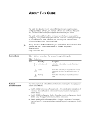
... necessary for your switch. It assumes a working knowledge of command line interface (CLI) commands that are required for configuring, using the supported protocols and CLI commands. ■ Switch 4800G Quick Reference Guides - Provides a summary of local area network (LAN) operations and familiarity with communication protocols that are used throughout this guide. Information that alerts you to software and product documentation: http://www.3com.com Table 1 lists icon conventions that describes important features or instructions. n Always download the Release...
... necessary for your switch. It assumes a working knowledge of command line interface (CLI) commands that are required for configuring, using the supported protocols and CLI commands. ■ Switch 4800G Quick Reference Guides - Provides a summary of local area network (LAN) operations and familiarity with communication protocols that are used throughout this guide. Information that alerts you to software and product documentation: http://www.3com.com Table 1 lists icon conventions that describes important features or instructions. n Always download the Release...
Getting Started Guide
Page 7
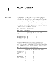
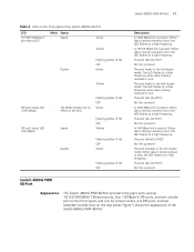
...used for connecting server groups in data centers. Table 2 lists the models of 1000Base-X SFP console ports ports 4 1 4 4 4 24 Together with an auto-sensing 10/100/1000BASE-T Ethernet port, each Combo port, either the SFP port or the auto-sensing 10/100/1000BASE-T Ethernet port can be used at the convergence or access layer of enterprise networks and metropolitan area networks (MANs). 1 PRODUCT OVERVIEW Introduction 3Com Switch 4800G Family (hereinafter referred to as 3Com). The Switch 4800G support diversified service features, IPv6 forwarding, and routing...
...used for connecting server groups in data centers. Table 2 lists the models of 1000Base-X SFP console ports ports 4 1 4 4 4 24 Together with an auto-sensing 10/100/1000BASE-T Ethernet port, each Combo port, either the SFP port or the auto-sensing 10/100/1000BASE-T Ethernet port can be used at the convergence or access layer of enterprise networks and metropolitan area networks (MANs). 1 PRODUCT OVERVIEW Introduction 3Com Switch 4800G Family (hereinafter referred to as 3Com). The Switch 4800G support diversified service features, IPv6 forwarding, and routing...
Getting Started Guide
Page 11
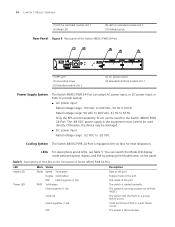
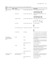
... LED flashes at a high frequency. The port fails the POST. Switch 4800G PWR 48-Port Appearance The Switch 4800G PWR 48-Port provides forty-eight auto-sensing 10/100/1000BASE-T Ethernet ports, four 1000Base-X SFP ports, and one console port on the front panel, and one AC power socket, one RPS port, and two extended module slots on the LED. The port works in the full duplex mode. No link is present. Switch 4800G PWR 48-Port 11 Table 4 LEDs on...
... LED flashes at a high frequency. The port fails the POST. Switch 4800G PWR 48-Port Appearance The Switch 4800G PWR 48-Port provides forty-eight auto-sensing 10/100/1000BASE-T Ethernet ports, four 1000Base-X SFP ports, and one console port on the front panel, and one AC power socket, one RPS port, and two extended module slots on the LED. The port works in the full duplex mode. No link is present. Switch 4800G PWR 48-Port 11 Table 4 LEDs on...
Getting Started Guide
Page 14
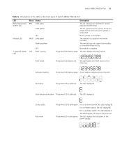
... six fans for heat dissipation. Table 5 Descriptions of the LEDs on the front panel of Switch 4800G PWR 24-Port LED Mode LED Power LED Mark Status Mode Speed Solid green Duplex Solid yellow PoE Flashing green (1 Hz) PWR Solid green Flashing green (1 Hz) Solid red Flashing yellow (1 Hz) OFF Description Rate of the port Duplex mode of the port PoE mode of the Switch 4800G PWR 24-Port (1) (2) (3) (4) (5) (1) RPS port (3) Grounding screw (5) Extended module slot 2 (2) AC power socket (4) Extended interface module slot 1 Power Supply System The Switch 4800G PWR 24-Port can...
... six fans for heat dissipation. Table 5 Descriptions of the LEDs on the front panel of Switch 4800G PWR 24-Port LED Mode LED Power LED Mark Status Mode Speed Solid green Duplex Solid yellow PoE Flashing green (1 Hz) PWR Solid green Flashing green (1 Hz) Solid red Flashing yellow (1 Hz) OFF Description Rate of the port Duplex mode of the port PoE mode of the Switch 4800G PWR 24-Port (1) (2) (3) (4) (5) (1) RPS port (3) Grounding screw (5) Extended module slot 2 (2) AC power socket (4) Extended interface module slot 1 Power Supply System The Switch 4800G PWR 24-Port can...
Getting Started Guide
Page 15
... 24-Port 15 Table 5 Descriptions of the LEDs on the front panel of the power supply. 81 - 100% 61 - 80% 41 - 60% 21 - 40% 0 - 20% For a command switch, the LED displays C. The LED displays 1 if there is connected. No DC power is only one unit. A bar rotates clockwise around the LED. The LED displays t. The switch does not support the module or a module failure occurs. Software loading The power LED flashes green. Fan...
... 24-Port 15 Table 5 Descriptions of the LEDs on the front panel of the power supply. 81 - 100% 61 - 80% 41 - 60% 21 - 40% 0 - 20% For a command switch, the LED displays C. The LED displays 1 if there is connected. No DC power is only one unit. A bar rotates clockwise around the LED. The LED displays t. The switch does not support the module or a module failure occurs. Software loading The power LED flashes green. Fan...
Getting Started Guide
Page 16
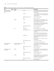
... present. The required power of Switch 4800G PWR 24-Port LED Mark Status 10/100/1000Base-T Ethernet port status LED Speed Duplex PoE Green Yellow Flashing yellow (3 Hz) OFF Green Yellow Flashing yellow (3 Hz) OFF Solid green Flashing green (1 Hz) Solid yellow SFP port status LED (1000 Mbps) SFP port status LED (100 Mbps) Flashing yellow (3 Hz) OFF The Mode button has no Green effect on the LED. A 1000 Mbps link is present. When data is being received or sent, the LED flashes at a high frequency. When...
... present. The required power of Switch 4800G PWR 24-Port LED Mark Status 10/100/1000Base-T Ethernet port status LED Speed Duplex PoE Green Yellow Flashing yellow (3 Hz) OFF Green Yellow Flashing yellow (3 Hz) OFF Solid green Flashing green (1 Hz) Solid yellow SFP port status LED (1000 Mbps) SFP port status LED (100 Mbps) Flashing yellow (3 Hz) OFF The Mode button has no Green effect on the LED. A 1000 Mbps link is present. When data is being received or sent, the LED flashes at a high frequency. When...
Getting Started Guide
Page 21
... full duplex mode. Switch 4800G 48-Port 21 Table 6 Description of LEDs on the LED. Over-temperature alarm The power LED is being received or sent, the LED flashes at a high frequency. When data is solid red. POST failed The power LED flashes red. The LED flashes the POST test ID of the Switch 4800G 48-Port LED 7-segment digital LED Mark Status Unit POST running Description The power LED flashes green. Software loading The power LED flashes green. A bar rotates clockwise around the LED. Fan...
... full duplex mode. Switch 4800G 48-Port 21 Table 6 Description of LEDs on the LED. Over-temperature alarm The power LED is being received or sent, the LED flashes at a high frequency. When data is solid red. POST failed The power LED flashes red. The LED flashes the POST test ID of the Switch 4800G 48-Port LED 7-segment digital LED Mark Status Unit POST running Description The power LED flashes green. Software loading The power LED flashes green. A bar rotates clockwise around the LED. Fan...
Getting Started Guide
Page 24
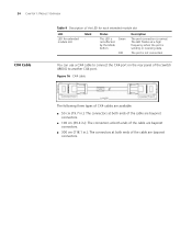
Status This LED is normal. Green OFF Description The port connection is not affected by the Mode button. You can use a CX4 cable to connect the CX4 port on the rear panel of the cable are bayonet connectors. ■ 300 cm (118.1 in.): The connectors at both ends of the Switch 4800G to another CX4 port. The LED flashes at both ends of the cable are bayonet connectors. The...
Status This LED is normal. Green OFF Description The port connection is not affected by the Mode button. You can use a CX4 cable to connect the CX4 port on the rear panel of the cable are bayonet connectors. ■ 300 cm (118.1 in.): The connectors at both ends of the Switch 4800G to another CX4 port. The LED flashes at both ends of the cable are bayonet connectors. The...
Getting Started Guide
Page 26
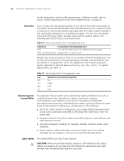
... high-frequency devices. ■ Use electromagnetic shielding, for example, shielded interface cables, when necessary. ■ Route interface cables only indoors to prevent signal ports from the optical fiber may hurt your eyes. For specific requirements, see Table 11. Laser Safety The Switch 4800G are rigorous limits on the Switch 4800G is more likely to happen. c CAUTION: When an optional interface module or SFP module on the content of harmful...
... high-frequency devices. ■ Use electromagnetic shielding, for example, shielded interface cables, when necessary. ■ Route interface cables only indoors to prevent signal ports from the optical fiber may hurt your eyes. For specific requirements, see Table 11. Laser Safety The Switch 4800G are rigorous limits on the Switch 4800G is more likely to happen. c CAUTION: When an optional interface module or SFP module on the content of harmful...
Getting Started Guide
Page 29
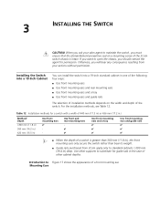
...; Use front mounting ears and guide rails The selection of installation methods depends on a mounting screw of the 3Com switch chassis is greater than 300 mm (11.8 in ) deep. Introduction to Figure 17 shows the appearance of other cabinet depths. Mounting Ears Use other supports to substitute for guide rails in ) Use front mounting ears ✔ - - Use front and rear mounting ears ✔ ✔ Use front mounting...
...; Use front mounting ears and guide rails The selection of installation methods depends on a mounting screw of the 3Com switch chassis is greater than 300 mm (11.8 in ) deep. Introduction to Figure 17 shows the appearance of other cabinet depths. Mounting Ears Use other supports to substitute for guide rails in ) Use front mounting ears ✔ - - Use front and rear mounting ears ✔ ✔ Use front mounting...
Getting Started Guide
Page 57
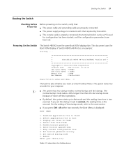
... Boot Menu... 0 The last line asks whether you set . Reboot Enter your response. Delete file from flash 5. the terminal (which can be a PC) used for your choice(0-9): Table 15 describes the fields above. Skip current configuration file 8. Set bootrom password recovery 9. Enter bootrom upgrade menu 7. Select application file to flash 2. Booting the Switch 57 Booting the Switch Checking before Power-On Before powering on the switch, verify that: ■ The power cable and grounding cable are properly connected. ■ The power supply...
... Boot Menu... 0 The last line asks whether you set . Reboot Enter your response. Delete file from flash 5. the terminal (which can be a PC) used for your choice(0-9): Table 15 describes the fields above. Skip current configuration file 8. Set bootrom password recovery 9. Enter bootrom upgrade menu 7. Select application file to flash 2. Booting the Switch 57 Booting the Switch Checking before Power-On Before powering on the switch, verify that: ■ The power cable and grounding cable are properly connected. ■ The power supply...
Getting Started Guide
Page 58
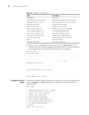
User interface aux0 is displayed: Auto-booting... 58 CHAPTER 4: INITIAL POWER-ON Table 15 Description on the fields Field BOOT MENU Download application file to flash Select application file to boot Display all files in flash Delete file from flash Modify bootrom password Enter bootrom upgrade menu Skip current configuration file Set bootrom password recovery Set switch startup mode Reboot Enter your choice(0-9): Description Boot menu Download the application files to the flash Select application files for switch booting Display all files in fast boot mode. Starting at ...
User interface aux0 is displayed: Auto-booting... 58 CHAPTER 4: INITIAL POWER-ON Table 15 Description on the fields Field BOOT MENU Download application file to flash Select application file to boot Display all files in flash Delete file from flash Modify bootrom password Enter bootrom upgrade menu Skip current configuration file Set bootrom password recovery Set switch startup mode Reboot Enter your choice(0-9): Description Boot menu Download the application files to the flash Select application files for switch booting Display all files in fast boot mode. Starting at ...
Getting Started Guide
Page 59
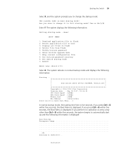
......... * * * 3Com Switch 4800G 48-Port BOOTROM, Version 205 * * * Copyright(c) 2004-2008 3Com Corporation. Starting at 0x80100000... Download application file to boot 3. Delete file from flash 5. Creation date : May 28 2007, 15:36:08 CPU Clock Speed : 533MHz BUS Clock Speed : 133MHz Memory Size : 256MB Mac Address : 00e0fc005502 Press Ctrl-B to enter Boot Menu... 0 In normal startup mode, the waiting time here is fast startup mode! Yes or No(Y/N) Enter Y. Skip current configuration file 8. Set bootrom password recovery 9. Reboot...
......... * * * 3Com Switch 4800G 48-Port BOOTROM, Version 205 * * * Copyright(c) 2004-2008 3Com Corporation. Starting at 0x80100000... Download application file to boot 3. Delete file from flash 5. Creation date : May 28 2007, 15:36:08 CPU Clock Speed : 533MHz BUS Clock Speed : 133MHz Memory Size : 256MB Mac Address : 00e0fc005502 Press Ctrl-B to enter Boot Menu... 0 In normal startup mode, the waiting time here is fast startup mode! Yes or No(Y/N) Enter Y. Skip current configuration file 8. Set bootrom password recovery 9. Reboot...
Getting Started Guide
Page 62
...+B. Set TFTP protocol parameter 62 CHAPTER 5: LOADING THE BOOT ROM AND HOST SOFTWARE CPU Clock Speed : 533MHz BUS Clock Speed : 133MHz Memory Size : 256MB Mac Address : 00e0fc005502 Press Ctrl-B to transmit data packets. It supports two types of data packets (128 bytes and 1 KB), two check methods (checksum and CRC), and error packet retransmission mechanism (generally the maximum number of a receiving program and a sending program. Skip current configuration file 8. Loading BootROM software...
...+B. Set TFTP protocol parameter 62 CHAPTER 5: LOADING THE BOOT ROM AND HOST SOFTWARE CPU Clock Speed : 533MHz BUS Clock Speed : 133MHz Memory Size : 256MB Mac Address : 00e0fc005502 Press Ctrl-B to transmit data packets. It supports two types of data packets (128 bytes and 1 KB), two check methods (checksum and CRC), and error packet retransmission mechanism (generally the maximum number of a receiving program and a sending program. Skip current configuration file 8. Loading BootROM software...
Getting Started Guide
Page 68
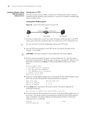
... TFTP server, and connect the switch through an Ethernet Port Introduction to TFTP Trivial file transfer protocol (TFTP), a protocol in the BootROM update menu to the Boot ROM update menu. Return to boot menu Enter your choice(0-9):" select 6 in the Boot Menu and then press Enter to provide unreliable data stream transfer service. 68 CHAPTER 5: LOADING THE BOOT ROM AND HOST SOFTWARE Loading Software Using TFTP through the console port to the configuration PC. Set...
... TFTP server, and connect the switch through an Ethernet Port Introduction to TFTP Trivial file transfer protocol (TFTP), a protocol in the BootROM update menu to the Boot ROM update menu. Return to boot menu Enter your choice(0-9):" select 6 in the Boot Menu and then press Enter to provide unreliable data stream transfer service. 68 CHAPTER 5: LOADING THE BOOT ROM AND HOST SOFTWARE Loading Software Using TFTP through the console port to the configuration PC. Set...
Getting Started Guide
Page 69
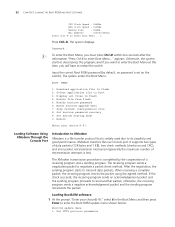
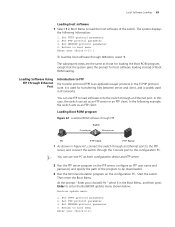
... be downloaded. 3 Run the terminal emulation program on the configuration PC. In this case, the switch can act as both configuration device and FTP server. 2 Run the FTP server program on the FTP server, configure an FTP user name and password, and specify the path of the switch. Set TFTP protocol parameter 2. Set XMODEM protocol parameter 0. Loading Boot ROM program Figure 67 Load BootROM software through FTP Switch Console port Ethernet port...
... be downloaded. 3 Run the terminal emulation program on the configuration PC. In this case, the switch can act as both configuration device and FTP server. 2 Run the FTP server program on the FTP server, configure an FTP user name and password, and specify the path of the switch. Set TFTP protocol parameter 2. Set XMODEM protocol parameter 0. Loading Boot ROM program Figure 67 Load BootROM software through FTP Switch Console port Ethernet port...
Getting Started Guide
Page 71
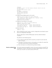
... the Flash memory before software downloading. ■ Power interruption is similar to the remote loading by Texas Imperial Software) ready for new user User(none):S5500 331 Give me your password, please Password: 230 Logged in successfully [ftp] get Switch 4800G.bin [ftp] get Switch 4800G.btm [ftp] bye 2 Update the Boot ROM program on the switch. Upgrade Bootrom succeeded! 3 Update the host software on the switch. Remote Software Loading 71 Connected. 220 WFTPD 2.0 service (by using TFTP...
... the Flash memory before software downloading. ■ Power interruption is similar to the remote loading by Texas Imperial Software) ready for new user User(none):S5500 331 Give me your password, please Password: 230 Logged in successfully [ftp] get Switch 4800G.bin [ftp] get Switch 4800G.btm [ftp] bye 2 Update the Boot ROM program on the switch. Upgrade Bootrom succeeded! 3 Update the host software on the switch. Remote Software Loading 71 Connected. 220 WFTPD 2.0 service (by using TFTP...
Getting Started Guide
Page 73
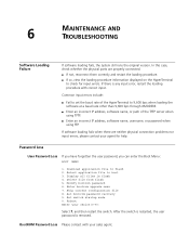
... the physical ports are neither physical connection problems nor input errors, please contact your choice(0-9): Select 7, and then restart the switch. Delete file from flash 5. Enter bootrom upgrade menu 7. Select application file to check for help. Display all files in flash 4. BootROM Password Loss Please contact with correct input. Set switch startup mode 0. 6 MAINTENANCE AND TROUBLESHOOTING Software Loading Failure If software loading fails, the system still runs the original version. Reboot Enter your...
... the physical ports are neither physical connection problems nor input errors, please contact your choice(0-9): Select 7, and then restart the switch. Delete file from flash 5. Enter bootrom upgrade menu 7. Select application file to check for help. Display all files in flash 4. BootROM Password Loss Please contact with correct input. Set switch startup mode 0. 6 MAINTENANCE AND TROUBLESHOOTING Software Loading Failure If software loading fails, the system still runs the original version. Reboot Enter your...
Getting Started Guide
Page 79
... roll out network-wide configuration changes with its intelligent VLAN configuration tools and the powerful template based configuration tools. By using 3ND you to carry out key management and administrative tasks on the network. B 3COM NETWORK MANAGEMENT 3Com Network Supervisor 3Com Network Director 3Com has a range of network management applications to address networks of all your network is configured with intelligent defaults and the ability to detect network misconfigurations. It can discover, map, and monitor all sizes and complexity...
... roll out network-wide configuration changes with its intelligent VLAN configuration tools and the powerful template based configuration tools. By using 3ND you to carry out key management and administrative tasks on the network. B 3COM NETWORK MANAGEMENT 3Com Network Supervisor 3Com Network Director 3Com has a range of network management applications to address networks of all your network is configured with intelligent defaults and the ability to detect network misconfigurations. It can discover, map, and monitor all sizes and complexity...


