Quick Installation Guide
Page 1
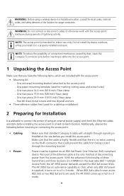
... 802.11n Managed Access Point 3CRWX395075A The 3Com AP3950 Managed Access Point provides IEEE 802.11n/b/g, and 802.11n/a wireless access to a Gigabit Ethernet port. You must have a wireless controller device to the access point: • 3Com WX4400 • 3Com WX2200 • 3Com WX1200 • 3Com WXR100 Power is recommended that the AP 3950 be connected to operate the access point. All configuration for the access point takes place on the 3Com Wireless LAN Controller...
... 802.11n Managed Access Point 3CRWX395075A The 3Com AP3950 Managed Access Point provides IEEE 802.11n/b/g, and 802.11n/a wireless access to a Gigabit Ethernet port. You must have a wireless controller device to the access point: • 3Com WX4400 • 3Com WX2200 • 3Com WX1200 • 3Com WXR100 Power is recommended that the AP 3950 be connected to operate the access point. All configuration for the access point takes place on the 3Com Wireless LAN Controller...
Quick Installation Guide
Page 2
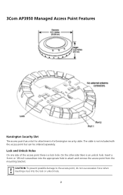
... access point, do not use excessive force when inserting a tool into the appropriate hole to attach and remove the access point from the mounting bracket. The cable is an unlock hole. Lock and Unlock Holes On one side of a Kensington security cable. 3Com AP3950 Managed Access Point Features Kensington Security Slot The access point has a slot for attachment of the access point...
... access point, do not use excessive force when inserting a tool into the appropriate hole to attach and remove the access point from the mounting bracket. The cable is an unlock hole. Lock and Unlock Holes On one side of a Kensington security cable. 3Com AP3950 Managed Access Point Features Kensington Security Slot The access point has a slot for attachment of the access point...
Quick Installation Guide
Page 3
.... 3 You can provide full power to the WXR100 or WX1200 wireless controller as pre-802.3at, switch or injector to equipment meeting these controllers only have 10/100 ports. WARNING: Do not operate the access point near unshielded blasting caps or in full 3 x 3 MIMO mode...other applicable national or international safety requirements for redundancy. Only if the boot attempt on port 2. Since the AP 3950 is a dual radio 802.11a/b/g/n access point, its power draw is not recommend that the antenna is operational. The ports are identical except for supplying additional ...
.... 3 You can provide full power to the WXR100 or WX1200 wireless controller as pre-802.3at, switch or injector to equipment meeting these controllers only have 10/100 ports. WARNING: Do not operate the access point near unshielded blasting caps or in full 3 x 3 MIMO mode...other applicable national or international safety requirements for redundancy. Only if the boot attempt on port 2. Since the AP 3950 is a dual radio 802.11a/b/g/n access point, its power draw is not recommend that the antenna is operational. The ports are identical except for supplying additional ...
Quick Installation Guide
Page 4
... Two #6 sheet metal screws and two drywall anchors • Three adhesive rubber feet (used , the AP 3950 comes up in this dual radio 802.11a/b/g/n Access Point, the AP 3950 power demands exceed the 802.3af power limits. With the advanced functionality of disconnecting power from being routed through ...the RJ-45 connector that there is advisable to connect the power (if using a wireless device in a 2 x 3 mode. Removal of the Ethernet cable is installed at the site before mounting or connecting the access point: • Cabling • Power Make sure that , when only 802.3af power...
... Two #6 sheet metal screws and two drywall anchors • Three adhesive rubber feet (used , the AP 3950 comes up in this dual radio 802.11a/b/g/n Access Point, the AP 3950 power demands exceed the 802.3af power limits. With the advanced functionality of disconnecting power from being routed through ...the RJ-45 connector that there is advisable to connect the power (if using a wireless device in a 2 x 3 mode. Removal of the Ethernet cable is installed at the site before mounting or connecting the access point: • Cabling • Power Make sure that , when only 802.3af power...

Quick Installation Guide
Page 5
flush ceiling tiles • Suspended ceiling - Additional MAC address labels are shipped with the access point. 3 Mounting the Access Point The access point can be mounted on the back of surfaces: • Suspended ceiling - drop ceiling tiles • Junction box • Solid wall or ceiling • Tabletop 5 • MAC Address Record the access point MAC address in a safe place before the access point is printed on the following types of the access point. The MAC address is installed in a hard-to-reach location.
flush ceiling tiles • Suspended ceiling - Additional MAC address labels are shipped with the access point. 3 Mounting the Access Point The access point can be mounted on the back of surfaces: • Suspended ceiling - drop ceiling tiles • Junction box • Solid wall or ceiling • Tabletop 5 • MAC Address Record the access point MAC address in a safe place before the access point is printed on the following types of the access point. The MAC address is installed in a hard-to-reach location.

Quick Installation Guide
Page 6
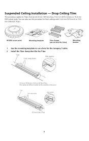
... sheath such as the one shown in the receptacle on the access point. Drop Ceiling Tiles" on the access point cannot accept a Category 5 cable that are 23.9 mm (15/16 inches) wide. TM AP39M50obacilciteyss point point MoMuonutintgintgemplate template MouMntoinugntbinragcket bracket 1 Use the mounting template to "Suspended...inch) or 15.9-mm (5/8-inch) T-bar, go to cut a hole for the Category 5 cable. 2 Remove the mounting bracket from the access point. 840-9502-0011 840-9502-0008 6 Cable Requirement The Ethernet ports on page 8. Use a Category 5 cable with an even sheath instead....
... sheath such as the one shown in the receptacle on the access point. Drop Ceiling Tiles" on the access point cannot accept a Category 5 cable that are 23.9 mm (15/16 inches) wide. TM AP39M50obacilciteyss point point MoMuonutintgintgemplate template MouMntoinugntbinragcket bracket 1 Use the mounting template to "Suspended...inch) or 15.9-mm (5/8-inch) T-bar, go to cut a hole for the Category 5 cable. 2 Remove the mounting bracket from the access point. 840-9502-0011 840-9502-0008 6 Cable Requirement The Ethernet ports on page 8. Use a Category 5 cable with an even sheath instead....

Quick Installation Guide
Page 7
Universal mounting bracket T-bar Port connector opening Universal mounting bracket T-bar 840-9502-0005 Port connector opening (Viewed from above ceiling tiles, looking down.) 4 Insert the Category 5 cable through the port connector opening in the mounting bracket, then plug the cable into the access point. 840-9502-0002 TM 5 Attach the access point to the T-bar clamp. 3 Attach the mounting bracket to the mounting bracket Lock T-bar TM 7 840-9502-0006 TM
Universal mounting bracket T-bar Port connector opening Universal mounting bracket T-bar 840-9502-0005 Port connector opening (Viewed from above ceiling tiles, looking down.) 4 Insert the Category 5 cable through the port connector opening in the mounting bracket, then plug the cable into the access point. 840-9502-0002 TM 5 Attach the access point to the T-bar clamp. 3 Attach the mounting bracket to the mounting bracket Lock T-bar TM 7 840-9502-0006 TM
Quick Installation Guide
Page 8
....9 mm (5/8 inches) wide. T-bar T-bar clamp halves Slide together 840-9502-0003 23.9-mm (15/16-in) or 14.2-mm (9/16-in ) T-bar 8 TM AP3950Maocbcielistsypoint point MouMnotiunngtitnegmplate template T-Tb-baar rcclalammppss (u(suesesseettththaattfiftistsTT-bar) MMoouunntitnigng bbraracckkeett 1 Use the mounting template to T-bars that fits the T-bar. Suspended Ceiling Installation - Drop Ceiling Tiles...
....9 mm (5/8 inches) wide. T-bar T-bar clamp halves Slide together 840-9502-0003 23.9-mm (15/16-in) or 14.2-mm (9/16-in ) T-bar 8 TM AP3950Maocbcielistsypoint point MouMnotiunngtitnegmplate template T-Tb-baar rcclalammppss (u(suesesseettththaattfiftistsTT-bar) MMoouunntitnigng bbraracckkeett 1 Use the mounting template to T-bars that fits the T-bar. Suspended Ceiling Installation - Drop Ceiling Tiles...

Quick Installation Guide
Page 9
Universal mounting bracket T- bar Port connector opening 840-9502-0012 T-bar clamps (attached to the T-bar clamp. 3 Remove the mounting bracket from above ceiling tiles, looking down.) Universal mounting bracket T-bar 5 Insert the Category 5 cable through the port connector opening (Viewed from the access point. 840-9502-0011 840-9502-0008 4 Attach the mounting bracket to T-bar) Port connector opening in the mounting bracket, then plug the cable into the access point. 840-9502-0002 TM 9
Universal mounting bracket T- bar Port connector opening 840-9502-0012 T-bar clamps (attached to the T-bar clamp. 3 Remove the mounting bracket from above ceiling tiles, looking down.) Universal mounting bracket T-bar 5 Insert the Category 5 cable through the port connector opening (Viewed from the access point. 840-9502-0011 840-9502-0008 4 Attach the mounting bracket to T-bar) Port connector opening in the mounting bracket, then plug the cable into the access point. 840-9502-0002 TM 9

Quick Installation Guide
Page 10
Lock T-bar 840-9502-0006 TM TM Junction Box Installation TM Mobility AP395p0oaincctess point MMoouunnttiningg bbrraacckkeett Mounting hardware Mounting hardware 1 Remove the mounting bracket from the access point. 840-9502-0011 840-9502-0008 10 6 Attach the access point to the mounting bracket.
Lock T-bar 840-9502-0006 TM TM Junction Box Installation TM Mobility AP395p0oaincctess point MMoouunnttiningg bbrraacckkeett Mounting hardware Mounting hardware 1 Remove the mounting bracket from the access point. 840-9502-0011 840-9502-0008 10 6 Attach the access point to the mounting bracket.

Quick Installation Guide
Page 11
TM Lock 11 840-9502-0062 840-9502-0017 TM 2 Attach the bracket to the mounting bracket. Junction box Port connector opening 3 Plug the Category 5 cable into the access point and attach the access point to the junction box.
TM Lock 11 840-9502-0062 840-9502-0017 TM 2 Attach the bracket to the mounting bracket. Junction box Port connector opening 3 Plug the Category 5 cable into the access point and attach the access point to the junction box.
Quick Installation Guide
Page 12
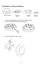
Solid Wall or Ceiling Installation TM AP39M5o0baiclictyess point point MoMuonutnintging temtepmlpaltaete MMouonutnintigng brbarcakceket t MMoouunnttiinngg hhaarrddwwaarree 1 Use the mounting template to cut a hole for the Category 5 cable. 2 Remove the mounting bracket from the access point. 840-9502-0011 840-9502-0008 3 Attach the bracket to the wall or ceiling. TM 12 840-9502-0015
Solid Wall or Ceiling Installation TM AP39M5o0baiclictyess point point MoMuonutnintging temtepmlpaltaete MMouonutnintigng brbarcakceket t MMoouunnttiinngg hhaarrddwwaarree 1 Use the mounting template to cut a hole for the Category 5 cable. 2 Remove the mounting bracket from the access point. 840-9502-0011 840-9502-0008 3 Attach the bracket to the wall or ceiling. TM 12 840-9502-0015

Quick Installation Guide
Page 13
840-9502-0016 TM 4 Plug the Category 5 cable into the access point and attach the access point to the mounting bracket. Cable TM Universal mounting bracket TM Lock 13 840-9502-0062
840-9502-0016 TM 4 Plug the Category 5 cable into the access point and attach the access point to the mounting bracket. Cable TM Universal mounting bracket TM Lock 13 840-9502-0062
Quick Installation Guide
Page 14
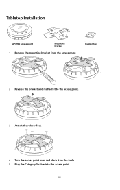
Tabletop Installation TM AP3M95o0bailictcyess point point MMouonutnintigng brbarcakckeett 1 Remove the mounting bracket from the access point. RRuubbbbeerr ffeeeett 840-9502-0008 840-9502-0011 2 Reverse the bracket and reattach it to the access point. 840-9502-0061 840-9502-0013 3 Attach the rubber feet. 4 Turn the access point over and place it on the table. 5 Plug the Category 5 cable into the access point. 14
Tabletop Installation TM AP3M95o0bailictcyess point point MMouonutnintigng brbarcakckeett 1 Remove the mounting bracket from the access point. RRuubbbbeerr ffeeeett 840-9502-0008 840-9502-0011 2 Reverse the bracket and reattach it to the access point. 840-9502-0061 840-9502-0013 3 Attach the rubber feet. 4 Turn the access point over and place it on the table. 5 Plug the Category 5 cable into the access point. 14
Quick Installation Guide
Page 15
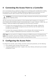
... the access point indirectly to a 3Com Wireless LAN Controller through the network, configure a Distributed Access Point connection on the controller. You can use Category 5 cable with the access point during periods of lightning activity. If the controller is already installed and configured for each access point connection. • To connect the access point directly to a 3Com Wireless LAN Controller, configure the controller port as an AP3950 managed access point...
... the access point indirectly to a 3Com Wireless LAN Controller through the network, configure a Distributed Access Point connection on the controller. You can use Category 5 cable with the access point during periods of lightning activity. If the controller is already installed and configured for each access point connection. • To connect the access point directly to a 3Com Wireless LAN Controller, configure the controller port as an AP3950 managed access point...
Quick Installation Guide
Page 16
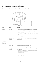
...client is booting and receiving its configuration file from a wireless controller. The access point is sending or receiving traffic. The radio is unable to receive boot instructions and a configuration file from a wireless controller. If the radio is enabled, no traffic activity...Solid amber Alternating green and amber Solid green Indicates • The access point has a valid management link with a wireless controller. • The access point has booted. • The access point has received a valid configuration from a wireless controller. • At least one radio is enabled or is ...
...client is booting and receiving its configuration file from a wireless controller. The access point is sending or receiving traffic. The radio is unable to receive boot instructions and a configuration file from a wireless controller. If the radio is enabled, no traffic activity...Solid amber Alternating green and amber Solid green Indicates • The access point has a valid management link with a wireless controller. • The access point has booted. • The access point has received a valid configuration from a wireless controller. • At least one radio is enabled or is ...
Quick Installation Guide
Page 17
...must maintain a minimum body-to-antenna distance of 20 cm. End users must ensure that the antenna is located or pointed such that may cause undesired operation. This equipment should be installed and operated with minimum distance 20 cm between the ...a particular installation. without obtaining a U.S. This product does not contain any other antenna or transmitter. Regulatory Information The 3Com® WLAN Managed Access Point AP3950 (M/N: AP3950; 3CRWX395075A) must be installed and used in strict accordance with the manufacturer's instructions as primary users of the 5.25 to ...
...must maintain a minimum body-to-antenna distance of 20 cm. End users must ensure that the antenna is located or pointed such that may cause undesired operation. This equipment should be installed and operated with minimum distance 20 cm between the ...a particular installation. without obtaining a U.S. This product does not contain any other antenna or transmitter. Regulatory Information The 3Com® WLAN Managed Access Point AP3950 (M/N: AP3950; 3CRWX395075A) must be installed and used in strict accordance with the manufacturer's instructions as primary users of the 5.25 to ...
Quick Installation Guide
Page 18
...01752-3064, USA (508) 323-5000 Date: July 1, 2008 Brand Name: 3Com Corporation M/N AP3950 Product Name: 3Com® WLAN Managed Access Point AP3950 Model Number: AP3950 SKU: 3CRWX395075A Equipment Type: WLAN Access Point Complies with Canadian ICES-003. 18 Operation is subject to the following two conditions...to operate this device must accept any radio or television interference caused by 3Com. RF Compliance This device complies with and/or damage this 3Com® WLAN Managed Access Point AP3950 (M/N: AP3950; 3CRWX395075A), or the substitution or attachment of the 5.25 to 5.35 GHz and...
...01752-3064, USA (508) 323-5000 Date: July 1, 2008 Brand Name: 3Com Corporation M/N AP3950 Product Name: 3Com® WLAN Managed Access Point AP3950 Model Number: AP3950 SKU: 3CRWX395075A Equipment Type: WLAN Access Point Complies with Canadian ICES-003. 18 Operation is subject to the following two conditions...to operate this device must accept any radio or television interference caused by 3Com. RF Compliance This device complies with and/or damage this 3Com® WLAN Managed Access Point AP3950 (M/N: AP3950; 3CRWX395075A), or the substitution or attachment of the 5.25 to 5.35 GHz and...
Quick Installation Guide
Page 19
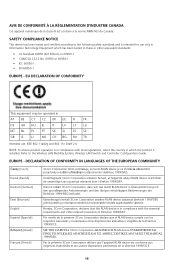
...RO TR Intended use only in Information Technology Equipment which has been tested to the Wireless LAN Mobility System, Wireless LAN Switch and Controller Configuration Guide. Käesolevaga kinnitab 3Com Corporation seadme RLAN device vastavust direktiivi 1999/5/EÜ põhinõuetele ja nimetatud ...grundlegenden Anforderungen und den übrigen einschlägigen Bestimmungen der Richtlinie 1999/5/EG befindet. Par la présente 3Com Corporation déclare que l'appareil RLAN device est conforme aux exigences essentielles et aux autres dispositions pertinentes de la ...
...RO TR Intended use only in Information Technology Equipment which has been tested to the Wireless LAN Mobility System, Wireless LAN Switch and Controller Configuration Guide. Käesolevaga kinnitab 3Com Corporation seadme RLAN device vastavust direktiivi 1999/5/EÜ põhinõuetele ja nimetatud ...grundlegenden Anforderungen und den übrigen einschlägigen Bestimmungen der Richtlinie 1999/5/EG befindet. Par la présente 3Com Corporation déclare que l'appareil RLAN device est conforme aux exigences essentielles et aux autres dispositions pertinentes de la ...
Quick Installation Guide
Page 20
... where noted below. • In Italy the end-user must apply for 3Com® WLAN Managed Access Point AP3950 at http://www.3com.com. Norsk [Norwegian] 3Com Corporation erklærer herved at http://support.3com.com/doc/AP3950_EU_DOC.pdf EU - Malti [Maltese] Hawnhekk, 3Com Corporation, jiddikjara li dan RLAN device jikkonforma mal-htigijiet essenzjali u ma provvedimenti ohrajn...
... where noted below. • In Italy the end-user must apply for 3Com® WLAN Managed Access Point AP3950 at http://www.3com.com. Norsk [Norwegian] 3Com Corporation erklærer herved at http://support.3com.com/doc/AP3950_EU_DOC.pdf EU - Malti [Maltese] Hawnhekk, 3Com Corporation, jiddikjara li dan RLAN device jikkonforma mal-htigijiet essenzjali u ma provvedimenti ohrajn...