Quick Installation Guide
Page 1
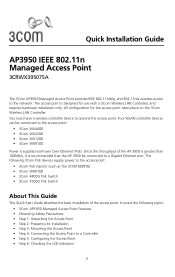
... 3Com PoE devices supply power to a Controller • Step 5: Configuring the Access Point • Step 6: Checking the LED Indicators 1 You must have a wireless controller device to the network. Quick Installation Guide AP3950 IEEE 802.11n Managed Access Point 3CRWX395075A The 3Com AP3950 Managed Access Point provides IEEE 802.11n/b/g, and 802.11n/a wireless access to operate the access point. Since the throughput of the access point. The access point is supplied via Power Over Ethernet (PoE). Four WLAN controller devices can be connected to the access point: • 3Com...
... 3Com PoE devices supply power to a Controller • Step 5: Configuring the Access Point • Step 6: Checking the LED Indicators 1 You must have a wireless controller device to the network. Quick Installation Guide AP3950 IEEE 802.11n Managed Access Point 3CRWX395075A The 3Com AP3950 Managed Access Point provides IEEE 802.11n/b/g, and 802.11n/a wireless access to operate the access point. Since the throughput of the access point. The access point is supplied via Power Over Ethernet (PoE). Four WLAN controller devices can be connected to the access point: • 3Com...
Quick Installation Guide
Page 2
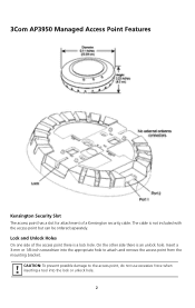
.... 2 On the other side there is a lock hole. 3Com AP3950 Managed Access Point Features Kensington Security Slot The access point has a slot for attachment of the access point there is an unlock hole. Lock and Unlock Holes On one side of a Kensington security cable. CAUTION: To prevent possible damage to the access point, do not use excessive force when inserting a tool into the appropriate...
.... 2 On the other side there is a lock hole. 3Com AP3950 Managed Access Point Features Kensington Security Slot The access point has a slot for attachment of the access point there is an unlock hole. Lock and Unlock Holes On one side of a Kensington security cable. CAUTION: To prevent possible damage to the access point, do not use excessive force when inserting a tool into the appropriate...
Quick Installation Guide
Page 3
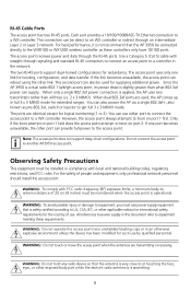
... extended ranges. All references to power supply in the network. WARNING: Do not touch or move the access point when the antennas are identical except for such use . For best performance, it is operational. The access point receives power and data through signaling and standard RJ-45 connectors to connect an access point to the WXR100 or WX1200 wireless controller as pre-802.3at, switch or injector to boot on port...
... extended ranges. All references to power supply in the network. WARNING: Do not touch or move the access point when the antennas are identical except for such use . For best performance, it is operational. The access point receives power and data through signaling and standard RJ-45 connectors to connect an access point to the WXR100 or WX1200 wireless controller as pre-802.3at, switch or injector to boot on port...
Quick Installation Guide
Page 4
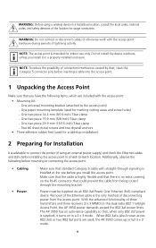
...) in full 3 x 3 mode. 4 WARNING: Before using an external power supply) and check the Ethernet cables and LEDs before installing the access point in a hazardous location, consult the local codes, national codes, and safety directors of the location for usage constraints. NOTE: To reduce the possibility of connection interference caused by dust, clean the Category 5 connector pins before inserting a cable into the access point. 1 Unpacking the Access Point Make sure that you...
...) in full 3 x 3 mode. 4 WARNING: Before using an external power supply) and check the Ethernet cables and LEDs before installing the access point in a hazardous location, consult the local codes, national codes, and safety directors of the location for usage constraints. NOTE: To reduce the possibility of connection interference caused by dust, clean the Category 5 connector pins before inserting a cable into the access point. 1 Unpacking the Access Point Make sure that you...

Quick Installation Guide
Page 5
Additional MAC address labels are shipped with the access point. 3 Mounting the Access Point The access point can be mounted on the back of surfaces: • Suspended ceiling - drop ceiling tiles • Junction box • Solid wall or ceiling • Tabletop 5 flush ceiling tiles • Suspended ceiling - The MAC address is installed in a safe place before the access point is printed on the following types of the access point. • MAC Address Record the access point MAC address in a hard-to-reach location.
Additional MAC address labels are shipped with the access point. 3 Mounting the Access Point The access point can be mounted on the back of surfaces: • Suspended ceiling - drop ceiling tiles • Junction box • Solid wall or ceiling • Tabletop 5 flush ceiling tiles • Suspended ceiling - The MAC address is installed in a safe place before the access point is printed on the following types of the access point. • MAC Address Record the access point MAC address in a hard-to-reach location.

Quick Installation Guide
Page 6
... This procedure applies to cut a hole for the Category 5 cable. 2 Remove the mounting bracket from the access point. 840-9502-0011 840-9502-0008 6 For a 14.2-mm (9/16-inch) or 15.9-mm (5/8-inch) T-bar, go to "Suspended Ceiling Installation - Cable Requirement The Ethernet ports on the access point. Use a Category 5 cable with an even sheath instead. Drop Ceiling Tiles" on page...
... This procedure applies to cut a hole for the Category 5 cable. 2 Remove the mounting bracket from the access point. 840-9502-0011 840-9502-0008 6 For a 14.2-mm (9/16-inch) or 15.9-mm (5/8-inch) T-bar, go to "Suspended Ceiling Installation - Cable Requirement The Ethernet ports on the access point. Use a Category 5 cable with an even sheath instead. Drop Ceiling Tiles" on page...

Quick Installation Guide
Page 7
Universal mounting bracket T-bar Port connector opening Universal mounting bracket T-bar 840-9502-0005 Port connector opening (Viewed from above ceiling tiles, looking down.) 4 Insert the Category 5 cable through the port connector opening in the mounting bracket, then plug the cable into the access point. 840-9502-0002 TM 5 Attach the access point to the T-bar clamp. 3 Attach the mounting bracket to the mounting bracket Lock T-bar TM 7 840-9502-0006 TM
Universal mounting bracket T-bar Port connector opening Universal mounting bracket T-bar 840-9502-0005 Port connector opening (Viewed from above ceiling tiles, looking down.) 4 Insert the Category 5 cable through the port connector opening in the mounting bracket, then plug the cable into the access point. 840-9502-0002 TM 5 Attach the access point to the T-bar clamp. 3 Attach the mounting bracket to the mounting bracket Lock T-bar TM 7 840-9502-0006 TM

Quick Installation Guide
Page 9
bar Port connector opening in the mounting bracket, then plug the cable into the access point. 840-9502-0002 TM 9 3 Remove the mounting bracket from the access point. 840-9502-0011 840-9502-0008 4 Attach the mounting bracket to T-bar) Port connector opening (Viewed from above ceiling tiles, looking down.) Universal mounting bracket T-bar 5 Insert the Category 5 cable through the port connector opening 840-9502-0012 T-bar clamps (attached to the T-bar clamp. Universal mounting bracket T-
bar Port connector opening in the mounting bracket, then plug the cable into the access point. 840-9502-0002 TM 9 3 Remove the mounting bracket from the access point. 840-9502-0011 840-9502-0008 4 Attach the mounting bracket to T-bar) Port connector opening (Viewed from above ceiling tiles, looking down.) Universal mounting bracket T-bar 5 Insert the Category 5 cable through the port connector opening 840-9502-0012 T-bar clamps (attached to the T-bar clamp. Universal mounting bracket T-

Quick Installation Guide
Page 10
Lock T-bar 840-9502-0006 TM TM Junction Box Installation TM Mobility AP395p0oaincctess point MMoouunnttiningg bbrraacckkeett Mounting hardware Mounting hardware 1 Remove the mounting bracket from the access point. 840-9502-0011 840-9502-0008 10 6 Attach the access point to the mounting bracket.
Lock T-bar 840-9502-0006 TM TM Junction Box Installation TM Mobility AP395p0oaincctess point MMoouunnttiningg bbrraacckkeett Mounting hardware Mounting hardware 1 Remove the mounting bracket from the access point. 840-9502-0011 840-9502-0008 10 6 Attach the access point to the mounting bracket.

Quick Installation Guide
Page 11
Junction box Port connector opening 3 Plug the Category 5 cable into the access point and attach the access point to the junction box. 840-9502-0017 TM 2 Attach the bracket to the mounting bracket. TM Lock 11 840-9502-0062
Junction box Port connector opening 3 Plug the Category 5 cable into the access point and attach the access point to the junction box. 840-9502-0017 TM 2 Attach the bracket to the mounting bracket. TM Lock 11 840-9502-0062
Quick Installation Guide
Page 12
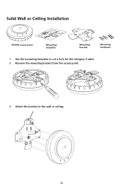
Solid Wall or Ceiling Installation TM AP39M5o0baiclictyess point point MoMuonutnintging temtepmlpaltaete MMouonutnintigng brbarcakceket t MMoouunnttiinngg hhaarrddwwaarree 1 Use the mounting template to cut a hole for the Category 5 cable. 2 Remove the mounting bracket from the access point. 840-9502-0011 840-9502-0008 3 Attach the bracket to the wall or ceiling. TM 12 840-9502-0015
Solid Wall or Ceiling Installation TM AP39M5o0baiclictyess point point MoMuonutnintging temtepmlpaltaete MMouonutnintigng brbarcakceket t MMoouunnttiinngg hhaarrddwwaarree 1 Use the mounting template to cut a hole for the Category 5 cable. 2 Remove the mounting bracket from the access point. 840-9502-0011 840-9502-0008 3 Attach the bracket to the wall or ceiling. TM 12 840-9502-0015

Quick Installation Guide
Page 13
840-9502-0016 TM 4 Plug the Category 5 cable into the access point and attach the access point to the mounting bracket. Cable TM Universal mounting bracket TM Lock 13 840-9502-0062
840-9502-0016 TM 4 Plug the Category 5 cable into the access point and attach the access point to the mounting bracket. Cable TM Universal mounting bracket TM Lock 13 840-9502-0062
Quick Installation Guide
Page 14
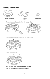
Tabletop Installation TM AP3M95o0bailictcyess point point MMouonutnintigng brbarcakckeett 1 Remove the mounting bracket from the access point. RRuubbbbeerr ffeeeett 840-9502-0008 840-9502-0011 2 Reverse the bracket and reattach it to the access point. 840-9502-0061 840-9502-0013 3 Attach the rubber feet. 4 Turn the access point over and place it on the table. 5 Plug the Category 5 cable into the access point. 14
Tabletop Installation TM AP3M95o0bailictcyess point point MMouonutnintigng brbarcakckeett 1 Remove the mounting bracket from the access point. RRuubbbbeerr ffeeeett 840-9502-0008 840-9502-0011 2 Reverse the bracket and reattach it to the access point. 840-9502-0061 840-9502-0013 3 Attach the rubber feet. 4 Turn the access point over and place it on the table. 5 Plug the Category 5 cable into the access point. 14
Quick Installation Guide
Page 15
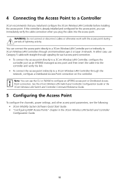
... Quick Start Guide. • "Configuring MAP Access Points" chapter in the 3Com Wireless LAN Switch and Controller Configuration Guide. 15 4 Connecting the Access Point to a Controller 3Com recommends that you can connect the access point directly to a 3Com Wireless LAN Controller port or indirectly to 3Com Wireless LAN Controllers through the network, configure a Distributed Access Point connection on the controller. WARNING: Do not connect or disconnect cables or otherwise work with straight-through signaling for the access point, you install and configure the 3Com Wireless LAN...
... Quick Start Guide. • "Configuring MAP Access Points" chapter in the 3Com Wireless LAN Switch and Controller Configuration Guide. 15 4 Connecting the Access Point to a Controller 3Com recommends that you can connect the access point directly to a 3Com Wireless LAN Controller port or indirectly to 3Com Wireless LAN Controllers through the network, configure a Distributed Access Point connection on the controller. WARNING: Do not connect or disconnect cables or otherwise work with straight-through signaling for the access point, you install and configure the 3Com Wireless LAN...
Quick Installation Guide
Page 16
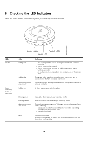
... radio has failed. 6 Checking the LED Indicators When the access point is connected to power, LEDs indicate activity as follows: TM 840-9502-0010 LEDs Health Radio 1 (2.4 GHz) Radio 2 (5.0 GHz) Radio 2 LED Radio 1 LED Health LED Color Solid green Solid amber Alternating green and amber Solid green Indicates • The access point has a valid management link with a wireless controller. • The access point has booted. • The access point has received a valid configuration from a wireless controller. • At least one radio is enabled...
... radio has failed. 6 Checking the LED Indicators When the access point is connected to power, LEDs indicate activity as follows: TM 840-9502-0010 LEDs Health Radio 1 (2.4 GHz) Radio 2 (5.0 GHz) Radio 2 LED Radio 1 LED Health LED Color Solid green Solid amber Alternating green and amber Solid green Indicates • The access point has a valid management link with a wireless controller. • The access point has booted. • The access point has received a valid configuration from a wireless controller. • At least one radio is enabled...
Quick Installation Guide
Page 17
... by the Federal Communications Commission helpful: The Interference Handbook 17 It is unlawful to 5.25 GHz frequency range. Export License. These radar stations can only be installed and operated with the supplied antenna(s). Regulatory Information The 3Com® WLAN Managed Access Point AP3950 (M/N: AP3950; 3CRWX395075A) must be determined by tuning the equipment off and on, the user is encouraged to try and...
... by the Federal Communications Commission helpful: The Interference Handbook 17 It is unlawful to 5.25 GHz frequency range. Export License. These radar stations can only be installed and operated with the supplied antenna(s). Regulatory Information The 3Com® WLAN Managed Access Point AP3950 (M/N: AP3950; 3CRWX395075A) must be determined by tuning the equipment off and on, the user is encouraged to try and...
Quick Installation Guide
Page 18
... interference, and (2) this device must accept any radio or television interference caused by such unauthorized modification, substitution or attachment will be the responsibility of connecting cables and equipment other users, the antenna type and its transmit antenna) that the Industry Canada technical specifications were met. Operation is available from windows to the licensed service, this 3Com® WLAN Managed Access Point AP3950 (M/N: AP3950; 3CRWX395075A), or the substitution...
... interference, and (2) this device must accept any radio or television interference caused by such unauthorized modification, substitution or attachment will be the responsibility of connecting cables and equipment other users, the antenna type and its transmit antenna) that the Industry Canada technical specifications were met. Operation is available from windows to the licensed service, this 3Com® WLAN Managed Access Point AP3950 (M/N: AP3950; 3CRWX395075A), or the substitution...
Quick Installation Guide
Page 19
..., declares that this RLAN device is installed. EUROPE - Hiermit erklärt 3Com Corporation, dass sich das Gerät RLAN device in compliance with the essential requirements and other equivalent standards: • UL Standard 60950 (3rd Edition) or 60950-1 • CAN/CSA C22.2 No. 60950 ...201;GLEMENTATION D'INDUSTRIE CANADA Cet appareil numérique de la classe B est conform à la norme NMB-003 du Canada. SAFETY COMPLIANCE NOTICE This device has been tested and certified according to the Wireless LAN Mobility System, Wireless LAN Switch and Controller Configuration Guide.
..., declares that this RLAN device is installed. EUROPE - Hiermit erklärt 3Com Corporation, dass sich das Gerät RLAN device in compliance with the essential requirements and other equivalent standards: • UL Standard 60950 (3rd Edition) or 60950-1 • CAN/CSA C22.2 No. 60950 ...201;GLEMENTATION D'INDUSTRIE CANADA Cet appareil numérique de la classe B est conform à la norme NMB-003 du Canada. SAFETY COMPLIANCE NOTICE This device has been tested and certified according to the Wireless LAN Mobility System, Wireless LAN Switch and Controller Configuration Guide.
Quick Installation Guide
Page 20
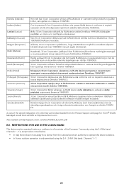
... de väsentliga egenskapskrav och övriga relevanta bestämmelser som framgår av direktiv 1999/5/ EG. RESTRICTIONS FOR USE IN THE 2.4GHz BAND This device may be downloaded from the Product Support web page for a license from the national spectrum authority to...of the European Community using the 2.4GHz band: Channels 1 - 13, except where noted below. • In Italy the end-user must apply for 3Com® WLAN Managed Access Point AP3950 at http://www.3com.com. Malti [Maltese] Hawnhekk, 3Com Corporation, jiddikjara li dan RLAN device jikkonforma mal-htigijiet essenzjali...
... de väsentliga egenskapskrav och övriga relevanta bestämmelser som framgår av direktiv 1999/5/ EG. RESTRICTIONS FOR USE IN THE 2.4GHz BAND This device may be downloaded from the Product Support web page for a license from the national spectrum authority to...of the European Community using the 2.4GHz band: Channels 1 - 13, except where noted below. • In Italy the end-user must apply for 3Com® WLAN Managed Access Point AP3950 at http://www.3com.com. Malti [Maltese] Hawnhekk, 3Com Corporation, jiddikjara li dan RLAN device jikkonforma mal-htigijiet essenzjali...
Quick Installation Guide
Page 21
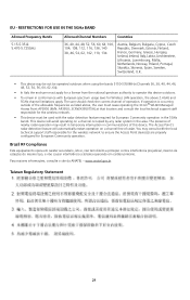
... user must cease operating the 3Com® WLAN Managed Access Point AP3950 (M/N: AP3950; 3CRWX395075A) at that location and consult the local technical support staff responsible for the wireless network. • This device must apply for a license from the national spectrum authority to ensure the Access Point device(s) are properly configured for European Community operation. The Access Point's radar detection feature will avoid operating on a channel free of this device outdoors...
... user must cease operating the 3Com® WLAN Managed Access Point AP3950 (M/N: AP3950; 3CRWX395075A) at that location and consult the local technical support staff responsible for the wireless network. • This device must apply for a license from the national spectrum authority to ensure the Access Point device(s) are properly configured for European Community operation. The Access Point's radar detection feature will avoid operating on a channel free of this device outdoors...


