
User Guide
Page 4
... 37 Viewing Trunk Information 37 Monitoring Traffic 38 Using the System Tools 39 Restarting the Switch 39 Resetting and Backing Up/Restoring Configuration 39 Upgrading the System Software 40 Configuring the ... 43 Forgotten Password 43 Forgotten Static IP Address 44 Solving LED Issues 44 If the Problem Persists 45 A OBTAINING SUPPORT FOR YOUR PRODUCT Register Your Product 47 Purchase Value-Added ... 47 Troubleshoot Online 47 Access Software Downloads 47 Telephone Technical Support and Repair 48 Contact Us 48 B SAFETY INFORMATION Important Safety Information 51 France and Peru Only 51 Power Cord ...
... 37 Viewing Trunk Information 37 Monitoring Traffic 38 Using the System Tools 39 Restarting the Switch 39 Resetting and Backing Up/Restoring Configuration 39 Upgrading the System Software 40 Configuring the ... 43 Forgotten Password 43 Forgotten Static IP Address 44 Solving LED Issues 44 If the Problem Persists 45 A OBTAINING SUPPORT FOR YOUR PRODUCT Register Your Product 47 Purchase Value-Added ... 47 Troubleshoot Online 47 Access Software Downloads 47 Telephone Technical Support and Repair 48 Contact Us 48 B SAFETY INFORMATION Important Safety Information 51 France and Peru Only 51 Power Cord ...

User Guide
Page 6
... comments about the current software release, including new features, modifications, and known problems. Documentation Comments Your suggestions are very important to us : ■ Document title ■ Document part number (on the title page) ■ Page number (if appropriate) Example: ■ 3Com Baseline Switch 2250 Plus User Guide ■ Part number: DUA16476B-SAA01 ■ Page 25 Please note...
... comments about the current software release, including new features, modifications, and known problems. Documentation Comments Your suggestions are very important to us : ■ Document title ■ Document part number (on the title page) ■ Page number (if appropriate) Example: ■ 3Com Baseline Switch 2250 Plus User Guide ■ Part number: DUA16476B-SAA01 ■ Page 25 Please note...
User Guide
Page 11
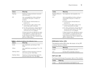
...Flashing Yellow to Port disabled or link loopback error Green Off Link not established, either nothing is connected to the port, or there is a problem. ■ Verify that the attached device is powered on ■ Verify that the cable or fiber is the correct type and is not faulty...not identify the cause of the problem, it may be that the unit or the device connected to the port is faulty. Contact your 3Com network supplier for further advice. (4) Module Active LEDs The Module Active LEDs show the status of the Switch. Contact your 3Com network supplier for further advice. ...
...Flashing Yellow to Port disabled or link loopback error Green Off Link not established, either nothing is connected to the port, or there is a problem. ■ Verify that the attached device is powered on ■ Verify that the cable or fiber is the correct type and is not faulty...not identify the cause of the problem, it may be that the unit or the device connected to the port is faulty. Contact your 3Com network supplier for further advice. (4) Module Active LEDs The Module Active LEDs show the status of the Switch. Contact your 3Com network supplier for further advice. ...

User Guide
Page 14
... Kit" on page 14), or it can cause reliability problems in your equipment. Do not place objects on page 13. CAUTION: If installing the Switch in . CAUTION: Before continuing, disconnect all cables from the underside of different size Baseline or SuperStack® 3 units, the smaller units must be...■ Die Luft so frei wie möglich von Staub ist. ■ Es unwahrscheinlich ist das die Betriebstemperatur überschritten wird. 3Com empfiehlt das Sie den Switch in der nähe von elektrischen Störquellen befinden. Do not have a free-standing stack of 25 mm or 1 in a...
... Kit" on page 14), or it can cause reliability problems in your equipment. Do not place objects on page 13. CAUTION: If installing the Switch in . CAUTION: Before continuing, disconnect all cables from the underside of different size Baseline or SuperStack® 3 units, the smaller units must be...■ Die Luft so frei wie möglich von Staub ist. ■ Es unwahrscheinlich ist das die Betriebstemperatur überschritten wird. 3Com empfiehlt das Sie den Switch in der nähe von elektrischen Störquellen befinden. Do not have a free-standing stack of 25 mm or 1 in a...
User Guide
Page 16
... green. Installing proper grounding helps to avoid damage from sags and surges to avoid unforeseen network outages. 3Com recommends that POST failed. When the Switch is clean and free from lightning and power surges. If the Power LED turns yellow after POST. Before...information. the only method of the Switch. Apply the pads to the Switch Power problems can be positioned at each other , you install power conditioning, especially in the marked area at the top. 16 CHAPTER 2: INSTALLING THE SWITCH mixing a variety of Baseline and SuperStack units, the smaller units...
... green. Installing proper grounding helps to avoid damage from sags and surges to avoid unforeseen network outages. 3Com recommends that POST failed. When the Switch is clean and free from lightning and power surges. If the Power LED turns yellow after POST. Before...information. the only method of the Switch. Apply the pads to the Switch Power problems can be positioned at each other , you install power conditioning, especially in the marked area at the top. 16 CHAPTER 2: INSTALLING THE SWITCH mixing a variety of Baseline and SuperStack units, the smaller units...
User Guide
Page 19
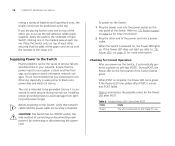
... SFP transceiver does not require powering off the Switch. Performing Spot Checks At frequent intervals, you ...lever toward you to the network using a duplex LC connector. If you experience any problems can give you should slide out easily. not click when you insert it, remove it... 1 Disconnect the cable from the front). The SFP transceiver should visually check the Switch. Attach a male duplex LC connector on the network cable into the duplex LC ... attended to when there will be least effect on the front of the Switch to the front right hand side of the cable to a device fitted ...
... SFP transceiver does not require powering off the Switch. Performing Spot Checks At frequent intervals, you ...lever toward you to the network using a duplex LC connector. If you experience any problems can give you should slide out easily. not click when you insert it, remove it... 1 Disconnect the cable from the front). The SFP transceiver should visually check the Switch. Attach a male duplex LC connector on the network cable into the duplex LC ... attended to when there will be least effect on the front of the Switch to the front right hand side of the cable to a device fitted ...
User Guide
Page 39
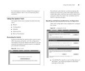
... you want to reboot their computers when the restart has completed and the Switch is operational again. For information on how to interpret the output on the port analyzer, refer to display the Configuration screen. Resetting and Backing Up/... 24 Restart Screen Using the System Tools 39 Any network users that are experiencing problems and you are currently accessing the Internet will be prompted to download and save a file to save the current configurations of the Switch. No configuration information will have their access interrupted while the restart takes place, and...
... you want to reboot their computers when the restart has completed and the Switch is operational again. For information on how to interpret the output on the port analyzer, refer to display the Configuration screen. Resetting and Backing Up/... 24 Restart Screen Using the System Tools 39 Any network users that are experiencing problems and you are currently accessing the Internet will be prompted to download and save a file to save the current configurations of the Switch. No configuration information will have their access interrupted while the restart takes place, and...
User Guide
Page 44
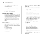
...link is connected, but the Link/Activity LED for the required link speed. Category 3 cables can be used for the port is a problem with this connection. Refer to "Approved SFP Transceivers" on page 18 for instructions. Solving LED Issues This section lists some issues that ...Discovery application, refer to the following topics in good condition. ■ The SFP module is correctly inserted. ■ A 3Com SFP module is poor After resetting the Switch, log on page 21. Category 5 cable is installed and correctly configured. 44 CHAPTER 5: TROUBLESHOOTING access. Verify that: ...
...link is connected, but the Link/Activity LED for the required link speed. Category 3 cables can be used for the port is a problem with this connection. Refer to "Approved SFP Transceivers" on page 18 for instructions. Solving LED Issues This section lists some issues that ...Discovery application, refer to the following topics in good condition. ■ The SFP module is correctly inserted. ■ A 3Com SFP module is poor After resetting the Switch, log on page 21. Category 5 cable is installed and correctly configured. 44 CHAPTER 5: TROUBLESHOOTING access. Verify that: ...

User Guide
Page 45
...connected to that accompanies the device for half-duplex operation All ports appear to show continual activity. Refer to the network. The Switch supports full-duplex autonegotiation. There may be broadcast storms on the same link. Some pieces of broadcast frames to the documentation ...that port is configured for half-duplex operation only. If the Problem Persists If the problem persists and the unit still does not operate successfully, contact your 3Com network supplier with the unit). ■ A brief description of the issue Ensure that ...
...connected to that accompanies the device for half-duplex operation All ports appear to show continual activity. Refer to the network. The Switch supports full-duplex autonegotiation. There may be broadcast storms on the same link. Some pieces of broadcast frames to the documentation ...that port is configured for half-duplex operation only. If the Problem Persists If the problem persists and the unit still does not operate successfully, contact your 3Com network supplier with the unit). ■ A brief description of the issue Ensure that ...

User Guide
Page 67
... matériel brouilleur du Canada. In order to meet FCC emissions limits, this equipment does cause interference to Identify and Resolve Radio-TV Interference Problems This booklet is available from the receiver. ■ Plug the equipment into a different outlet so that equipment and receiver are designed to provide reasonable protection...
... matériel brouilleur du Canada. In order to meet FCC emissions limits, this equipment does cause interference to Identify and Resolve Radio-TV Interference Problems This booklet is available from the receiver. ■ Plug the equipment into a different outlet so that equipment and receiver are designed to provide reasonable protection...


