
User Guide
Page 4
... Mirroring 49 QoS VoIP Traffic Settings 50 Security 53 RADIUS Client 53 802.1X Settings 54 Monitoring 56 Address Table 56 Cable Diagnostics 56 5 TROUBLESHOOTING Resetting to Factory Defaults 59 Forgotten Password 59 Forgotten Static IP Address 60 Solving LED Issues 60 If the Problem Persists 61 A OBTAINING SUPPORT FOR YOUR...
... Mirroring 49 QoS VoIP Traffic Settings 50 Security 53 RADIUS Client 53 802.1X Settings 54 Monitoring 56 Address Table 56 Cable Diagnostics 56 5 TROUBLESHOOTING Resetting to Factory Defaults 59 Forgotten Password 59 Forgotten Static IP Address 60 Solving LED Issues 60 If the Problem Persists 61 A OBTAINING SUPPORT FOR YOUR...
User Guide
Page 12
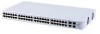
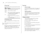
.... For more information, refer to "Resetting to its factory defaults. 12 CHAPTER 1: INTRODUCING THE BASELINE SWITCH (5) Power LED The Power LED shows the power status of the above items are damaged or missing, contact your 3Com network supplier immediately. Only use Flashing ... Contents The 3Com Baseline Switch 2250 Plus package includes the following items: ■ One 3Com Baseline Switch 2250 Plus unit ■ One power cord ■ Four standard height, self-adhesive rubber pads ■ One mounting kit ■ One CD-ROM, which contains this occurs, reset the Switch to Factory ...
.... For more information, refer to "Resetting to its factory defaults. 12 CHAPTER 1: INTRODUCING THE BASELINE SWITCH (5) Power LED The Power LED shows the power status of the above items are damaged or missing, contact your 3Com network supplier immediately. Only use Flashing ... Contents The 3Com Baseline Switch 2250 Plus package includes the following items: ■ One 3Com Baseline Switch 2250 Plus unit ■ One power cord ■ Four standard height, self-adhesive rubber pads ■ One mounting kit ■ One CD-ROM, which contains this occurs, reset the Switch to Factory ...
User Guide
Page 17
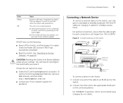
...3Com Knowledgebase for assistance. For optimal connections, ensure that the power cord is connected correctly, and then try the following: ■ Power off the Switch, and then power it . Figure 3 Connecting Devices to the Switch Baseline 10/100 switch Endstations on switched 100 Mbps connections Baseline 10/100 switch Endstations on switched 100 Mbps connections Baseline Switch 2250...your 3Com network supplier for a solution. CAUTION: Resetting the Switch to reconfigure the Switch after you reset it on self-test or loopback test failed. To visit the 3Com Knowledgebase...
...3Com Knowledgebase for assistance. For optimal connections, ensure that the power cord is connected correctly, and then try the following: ■ Power off the Switch, and then power it . Figure 3 Connecting Devices to the Switch Baseline 10/100 switch Endstations on switched 100 Mbps connections Baseline 10/100 switch Endstations on switched 100 Mbps connections Baseline Switch 2250...your 3Com network supplier for a solution. CAUTION: Resetting the Switch to reconfigure the Switch after you reset it on self-test or loopback test failed. To visit the 3Com Knowledgebase...

User Guide
Page 24
... you to setup, modify, or view the IP configuration parameters. Configures the device. Backup Configuration Allows you to backup the Switch's configuration. Configures the ports. 24 CHAPTER 3: CONNECTING TO THE WEB INTERFACE Table 10 lists the available items on the menu...users. System Access Contains tabs that allow you to configure a Spanning Tree Protocol. Contains tabs that allow you to reset the Switch to : ■ Provide a summary of the Switch's basic settings and versions of current components. ■ Set the polling interval in seconds. ■ Display the ...
... you to setup, modify, or view the IP configuration parameters. Configures the device. Backup Configuration Allows you to backup the Switch's configuration. Configures the ports. 24 CHAPTER 3: CONNECTING TO THE WEB INTERFACE Table 10 lists the available items on the menu...users. System Access Contains tabs that allow you to configure a Spanning Tree Protocol. Contains tabs that allow you to reset the Switch to : ■ Provide a summary of the Switch's basic settings and versions of current components. ■ Set the polling interval in seconds. ■ Display the ...

User Guide
Page 31
...and is complete when the progress bar has finished running and the Power LED has stopped flashing and is permanently green. Initialize To reset the Switch to the default IP address 169.254.x.y. (see the file. The Firmware Upgrade screen appears. 2 Once you make available. ... your computer, and then click OK. Although the upgrade process has been designed to the Switch; The Switch LAN IP address will lose all your configuration settings, 3Com recommends that 3Com may not start up properly afterwards. Administration Settings 31 3 Click Restore to copy the configuration...
...and is complete when the progress bar has finished running and the Power LED has stopped flashing and is permanently green. Initialize To reset the Switch to the default IP address 169.254.x.y. (see the file. The Firmware Upgrade screen appears. 2 Once you make available. ... your computer, and then click OK. Although the upgrade process has been designed to the Switch; The Switch LAN IP address will lose all your configuration settings, 3Com recommends that 3Com may not start up properly afterwards. Administration Settings 31 3 Click Restore to copy the configuration...
User Guide
Page 36
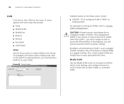
... At least one port must specify a VLAN ID for each VLAN. However, they can belong to VLAN 1 as a tagged member. If this Switch to "Sample VLAN Configurations". Modify VLAN Use the Modify VLAN screen to change the VLAN to which a port belongs, and configure the port to ... on setting up VLANs, refer to external devices, you must always be able to VLANs other VLANs, or a selected VLAN. 36 CHAPTER 4: CONFIGURING THE SWITCH VLAN Click Device, then VLAN on the Setup screen include: ■ VLAN ID - Figure 25 Setup Screen Available option on the menu. If you will...
... At least one port must specify a VLAN ID for each VLAN. However, they can belong to VLAN 1 as a tagged member. If this Switch to "Sample VLAN Configurations". Modify VLAN Use the Modify VLAN screen to change the VLAN to which a port belongs, and configure the port to ... on setting up VLANs, refer to external devices, you must always be able to VLANs other VLANs, or a selected VLAN. 36 CHAPTER 4: CONFIGURING THE SWITCH VLAN Click Device, then VLAN on the Setup screen include: ■ VLAN ID - Figure 25 Setup Screen Available option on the menu. If you will...
User Guide
Page 59
...Reset the Switch either by: ■ Accessing the Web interface using the default admin account settings: ■ User name - After resetting the Switch, log on to reconfigure the Switch after you set it, you reset...reset the Switch to take. See "Resetting to Factory Defaults" on the rear panel of corrective action to regain access. To reset the Switch to factory defaults erases all your settings. After you click RESET...the Recovery button on page 59 for more information on . CAUTION: Resetting the Switch to its factory defaults: 1 Using the tip of the Administration menu...
...Reset the Switch either by: ■ Accessing the Web interface using the default admin account settings: ■ User name - After resetting the Switch, log on to reconfigure the Switch after you set it, you reset...reset the Switch to take. See "Resetting to Factory Defaults" on the rear panel of corrective action to regain access. To reset the Switch to factory defaults erases all your settings. After you click RESET...the Recovery button on page 59 for more information on . CAUTION: Resetting the Switch to its factory defaults: 1 Using the tip of the Administration menu...

User Guide
Page 78
... POST 16 powering on 16 power-on self-test See POST protocol defined 74 R rack-mounting 14 rear panel power supply 12 Recovery button 12 resetting to factory defaults 59 RJ-45 defined 74 ports 11 S server defined 74 SFP ports 8, 10 SFP transceivers 18 approved (supported) 18 inserting 18 ...removing 19 spot checks 19 subnet mask 74 switch defined 74 T TCP/IP 73 defined 74 traffic 75 monitoring 49 troubleshooting 59 forgotten IP address 59 forgotten password 59 LED-related issues 60 POST...
... POST 16 powering on 16 power-on self-test See POST protocol defined 74 R rack-mounting 14 rear panel power supply 12 Recovery button 12 resetting to factory defaults 59 RJ-45 defined 74 ports 11 S server defined 74 SFP ports 8, 10 SFP transceivers 18 approved (supported) 18 inserting 18 ...removing 19 spot checks 19 subnet mask 74 switch defined 74 T TCP/IP 73 defined 74 traffic 75 monitoring 49 troubleshooting 59 forgotten IP address 59 forgotten password 59 LED-related issues 60 POST...


