
Owner's Manual
Page 198
... and replace the bulb. 198 MAINTAINING YOUR VEHICLE 2. Remove two screws from the headlight assembly and remove the assembly from behind the bumper fascia and grille. 3. NOTE: The headlight assembly is located to compress against the headlamp module housing.
... and replace the bulb. 198 MAINTAINING YOUR VEHICLE 2. Remove two screws from the headlight assembly and remove the assembly from behind the bumper fascia and grille. 3. NOTE: The headlight assembly is located to compress against the headlamp module housing.
Owner Manual
Page 200
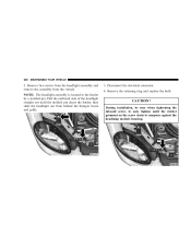
... screw starts to the fender by a molded pin. Remove two screws from the headlight assembly and remove the assembly from behind the bumper fascia and grille. 3. 200 MAINTAINING YOUR VEHICLE 2. NOTE: The headlight assembly is located to compress against the headlamp module housing. CAUTION!
... screw starts to the fender by a molded pin. Remove two screws from the headlight assembly and remove the assembly from behind the bumper fascia and grille. 3. 200 MAINTAINING YOUR VEHICLE 2. NOTE: The headlight assembly is located to compress against the headlamp module housing. CAUTION!
Owner Manual SRT-4
Page 174
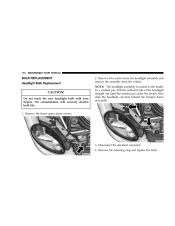
... three upper fascia screws. 3. Disconnect the electrical connector. 4. Remove two screws from the headlight assembly and remove the assembly from behind the bumper fascia and grille. NOTE: The headlight assembly is located to the fender by a molded pin. Pull the outboard side of the headlight straight out until the molded pin...
... three upper fascia screws. 3. Disconnect the electrical connector. 4. Remove two screws from the headlight assembly and remove the assembly from behind the bumper fascia and grille. NOTE: The headlight assembly is located to the fender by a molded pin. Pull the outboard side of the headlight straight out until the molded pin...