
Yamaha HTR-5920 Support Question
Yamaha HTR-5920 Support Question
Find answers below for this question about Yamaha HTR-5920.Need a Yamaha HTR-5920 manual? We have 1 online manual for this item!
Question posted by valeatasowell on June 10th, 2018
Cutting Off
I have a Yamaha htr-5920. How can I quick fix it from turning off when I turn it on. It turns off 2 seconds after I turn it on. Where is the fuse and how much does fuse cost
Current Answers
Related Yamaha HTR-5920 Manual Pages
Owners Manual - Page 3
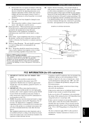
... 23 Heat - When replacement parts are required,
be determined by turning the unit "OFF" and "ON", please try to grounding electrodes... device that are on different branch (circuit breaker or fuse) circuits or install AC line filter/s. mance - Upon... installation instructions. Adjust only those products distributed by Yamaha may cause interference harmful to provide some protection against...
Owners Manual - Page 4
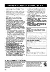
...components... heat radiation. YAMAHA will not be held responsible for any service is too late, YAMAHA and the Electronic...-down. Contact qualified YAMAHA service personnel when any...time (i.e. MODEL: Serial No.: The serial number is turned off by lightning, keep the power cord and outdoor ...YAMAHA and the Electronic Industries Association's Consumer Electronics Group want you to modify or...
Owners Manual - Page 5

...
CONNECTIONS 10 Placing speakers 10 Connecting speakers 11 Information on jacks and cable plugs 13 Connecting video components 14 Connecting audio components 16 Connecting the FM and AM antennas 17 Connecting the power cable 18 Turning on the power 18
SETUP 19
ADVANCED OPERATION
ADVANCED OPERATIONS 31 Using the sleep timer 31 Dimming the...
Owners Manual - Page 6
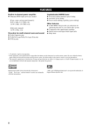
... capability (preset editing)
Other features ◆ A SET MENU that provides you with items for
optimizing this unit for your audio/video system ◆ Component video input/output capability ◆ Optical and coaxial digital audio signal jacks ◆ Sleep timer
• y indicates a tip for your operation. • Some operations can be performed by using...
Owners Manual - Page 8
...mode.
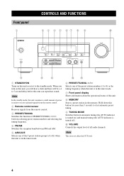
7 Front panel display Shows information about the operational status of all audio channels. Hold down this button for more than 3 seconds to start automatic preset tuning.
9 TUNING MODE Switches between FM and ...frequency.
4 FM/AM Switches the reception band between automatic tuning (the AUTO indicator is turned on) and manual tuning (the AUTO indicator is in the memory.
Note
This does...
Owners Manual - Page 9
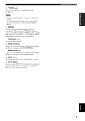
... source you connect headphones, no signals are output to the speakers.
• All Dolby Digital and DTS audio signals (except the LFE channel) are mixed down all Dolby Digital and DTS signals (except the LFE channel...with TONE CONTROL.
INTRODUCTION
A PHONES jack Outputs audio signals for the type of signals received when one component is connected via both digital and analog connections.
Owners Manual - Page 10
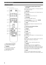
A POWER Turns on or off the night listening mode.
When you select "STEREO", this unit is in the tuner mode.
Press MUTE again to restore the audio output to be adjusted and...Select and adjust the SET MENU items.
9 LEVEL Selects the speaker channel to the previous volume level.
G NIGHT Turns on this unit. B SLEEP Sets the sleep timer. The night listening mode is in the tuner mode.
6 ...
Owners Manual - Page 12
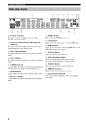
... the sleep timer is tuned into a station. C TUNED indicator Lights up when this unit is reproducing PCM (Pulse Code Modulation) digital audio signals. E Input channel indicators Indicate the channel components of the surround mode or the listening mode.
3 Input signal indicators The respective indicator lights up according to the input signal.
4 Band...
Owners Manual - Page 13
... DTV/CBL DVD
OUTPUT
DIGITAL INPUT
CENTER FRONT
R
L
PR
DVD DTV/CBL MONITOR OUT COMPONENT VIDEO
+
+
-
-
-
-
6ΩMIN./SPEAKER
CLASS 2 WIRING SPEAKERS
6ΩMIN./SPEAKER
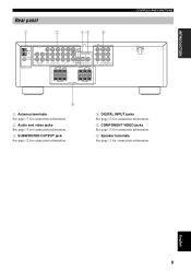
CONTROLS AND FUNCTIONS
6
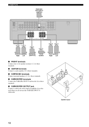
1 Antenna terminals See page 17 for connection information. 2 Audio and video jacks See page 13 for connection information. 3 SUBWOOFER OUTPUT jack See page 12...
Owners Manual - Page 15
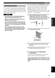
... Black: negative (-)
3 Insert one bare wire into the hole of each other or do not use the YAMAHA SW-P170 subwoofer, connect a subwoofer with a stripe, groove or ridges.
Cables are faulty, no sound will....
• Use magnetically shielded speakers. Connect the input jack of the speaker connections is turned off.
• Do not let the bare speaker wires touch each
terminal.
4 Release ...
Owners Manual - Page 16
...
75Ω UNBAL.
FM ANT
TUNER
L
R
IN
OUT
MD/CD-R
AUDIO
DVD DTV/CBL V-AUX
IN
OUT
VCR
SURROUND SUB
R
L WOOFER
+...SUB CD WOOFER DTV/CBL DVD
OUTPUT
DIGITAL INPUT
CENTER
FRONT
R
L
PR
DVD DTV/CBL MONITOR OUT COMPONENT VIDEO
+
+
-
-
-
- SPEAKERS
4
5
Surround speakers
Right Left
6
Subwoofer
(SW-P170)...the YAMAHA SW-P170 subwoofer (6) to this
jack when you do not use the...
Owners Manual - Page 17
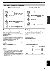
... can use the digital jacks to the left and right analog audio cables.
AUDIO jacks For conventional analog audio signals transmitted via a coaxial digital audio cable.
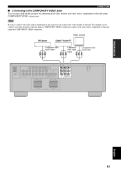
COMPONENT VIDEO jacks For component signals, separated into the luminance (Y) and chrominance (PB, PR) video signals transmitted on your other components.
Video signal flow for MONITOR OUT Input
Output (MONITOR OUT...
Owners Manual - Page 18
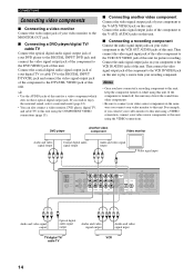
... OUT VIDEO jack of this unit for picture recording. Connect the audio signal output jacks on while using this unit.
If the component is turned off, this unit may distort the sound from other components.
• Be sure to connect your video source components in the same way you connect your video monitor to this...
Owners Manual - Page 19
FM ANT
TUNER
L
R
IN
OUT
MD/CD-R
AUDIO
DVD DTV/CBL V-AUX
IN
OUT
VCR
SURROUND SUB
R
L WOOFER
+
+
MONITOR OUT
Y
OPTICAL COAXIAL
PB
SUB CD WOOFER DTV/CBL DVD
OUTPUT
DIGITAL INPUT
CENTER
FRONT
R
L
PR
DVD DTV/CBL MONITOR OUT COMPONENT VIDEO
+
+
-
-
-
-
6ΩMIN./SPEAKER
CLASS 2 WIRING SPEAKERS
6ΩMIN./SPEAKER
English
15...
Owners Manual - Page 20
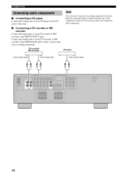
If the component is turned off, this unit.
CD recorder/ MD recorder
CD player
Audio signal output
Audio signal input
Audio signal output
L
R
L
R
L
R
VIDEO
AM ANT GND
75Ω UNBAL.
FM ANT
TUNER
L
R
IN
OUT
MD/CD-R
AUDIO
DVD DTV/CBL V-AUX
IN
OUT
VCR
SURROUND SUB
R
L WOOFER
+
+
MONITOR OUT
Y
OPTICAL COAXIAL
PB
SUB CD WOOFER DTV...
Owners Manual - Page 21
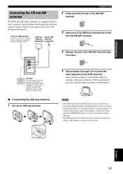
.... AM loop Indoor FM antenna antenna (supplied) (supplied)
CONNECTIONS
2 Press and hold the tab of the AM ANT
terminal.
3 Insert one . Consult the nearest authorized YAMAHA dealer or service center about outdoor antennas. • The AM loop antenna should provide sufficient signal strength. Outdoor AM antenna
Use a 5 to 10 m (16 to...
Owners Manual - Page 22
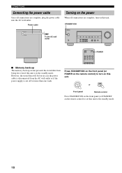
...STANDBY/ON on the front panel (or STANDBY on the remote control) to set this unit to turn on this unit is cut off for more than one week.
TUNER
P1
P2
P3
P4
Press STANDBY/ON on the front panel... are complete, plug the power cable into the AC wall outlet. Power cable
Turning on the power
When all connections are complete, turn on the remote control) to the standby mode.
18
Owners Manual - Page 37
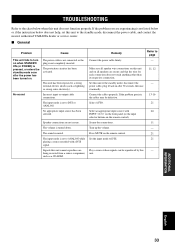
... are being received from a source component, such as lightning or strong static electricity).
This unit has been exposed to turn on when STANDBY/ ON (or POWER...seconds, then use it normally. Make sure all speakers are not secure. If the problem persists, the cables may be reproduced by this unit to the standby mode, disconnect the power cable, and contact the nearest authorized YAMAHA...
Owners Manual - Page 39
... heard.
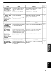
frozen by a power supply with a recording component. Move this unit. The picture is
distorted. turns into the standby high and the overheat protection circuitry turn it in
the front panel
The input mode is turned off.
played. (Dolby Digital signals. Firmly connect the audio plugs.
The source component is not connected to AUTO or DTS...
Owners Manual - Page 43
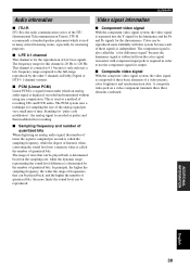
...determined based on a video component transmits these signals is independent. color, brightness and synchronization data. ITU-R recommends a standard speaker placement which an analog audio signal is digitized, recorded...The PCM system uses a technique for sampling the size of the analog signal per second is called the sampling frequency, while the degree of frequencies that can be played ...
Similar Questions

Stereo Wont Stay On
my Yamaha HTR-5920 will power on then shut off seconds later. I've unhooked everything from it and i...
my Yamaha HTR-5920 will power on then shut off seconds later. I've unhooked everything from it and i...
(Posted by jduling88 3 years ago)


What Are The Control Codes For Amp. Yamaha Htr-5920?
(Posted by normy002 13 years ago)