Troy-Bilt TB575 Support Question
Troy-Bilt TB575 Support Question
Find answers below for this question about Troy-Bilt TB575.Need a Troy-Bilt TB575 manual? We have 2 online manuals for this item!
Question posted by tamtmnguyen on June 25th, 2014
Remove Head On Tb575 Ec
I want to replace the head on my TB575 EC because it's broken. I have already taken the gear box off. Found a square key and grabbed with vise grips. But it's way to tied, I can't turn it. What can I do?
Current Answers
Related Troy-Bilt TB575 Manual Pages
Operation Manual - Page 1

...) DO NOT RETURN THE UNIT TO THE RETAILER. Failure to obtain a list of authorized service dealers near you to liability or a fine. If it requires replacement, ask your state or local authorities for later use. All information, illustrations, and specifications in Canada to follow the safety rules. CALIFORNIA PROPOSITION 65 WARNING...
Operation Manual - Page 2

...Remove all debris and hard or sharp objects such as glass, wire, etc.
• Be aware of the risk of injury to the head... original equipment manufacturer replacement parts and accessories ... touch the engine, gear housing or muffler. ... position. Use of any way. Clean after the engine...even after the unit is turned off and become dangerous ...shirt. Keep a firm grip on both hands when operating...
Operation Manual - Page 3

...product. You may appear on cutting attachment shield. Remove the screws and
bottom clamp piece that were installed... (6
in conjunction with a large Flat-head or T-25 Torx screwdriver. RULES FOR ...WARNING
Do not touch a hot muffler, gear housing or cylinder.
SYMBOL
MEANING
SYMBOL
MEANING... of the
shaft grip. Place it .
5.
Do not tighten until the D-handle is turned off.
•...
Operation Manual - Page 4

... Plug
bottle of the old gasoline in accordance to cool before each use of gum deposits. Replace the top.
NOTE: Never add oil to Checking the Oil Level. Wipe up to the instructions...the Oil. NOTE: Save the bottle of ignition for improper unit performance. Oil Fill Hole
2. Remove the oil fill plug from the area. Alcohol-blended fuel absorbs water. Avoid creating a source of...
Operation Manual - Page 6

...before removing or installing add-ons. Removing the... Cutting Attachment or Add-On 1.
EZ-Link™ Coupler
Release Button Primary Hole
WARNING: Before you begin using the line head cutting attachment with an electric powered unit.
2. Press and hold the release button (Fig. 9).
3. EZ-Link™ Coupler
Release Button
Upper Shaft Housing
Lower Shaft Housing
Fig. 10
3. Turn...
Operation Manual - Page 7

...cutting attachment shield will make the clutch overheat. ADJUSTING TRIMMING LINE LENGTH
The Bump Head™ cutting attachment allows you to release trimming line without the need to the...away from right to left hand holding the shaft grip • The operator's left arm is parallel to bend over 8 inches (200 mm) by removing all vegetation around a tree. OPERATING INSTRUCTIONS
HOLDING ...
Operation Manual - Page 8

...With New Line
NOTE: It Is unnecessary to remove the bump knob to ensure that the unit...WARNING: Always use original equipment manufacturer 0.095 inch (2.41 mm) replacement line. MAINTENANCE AND REPAIR INSTRUCTIONS
WARNING: To prevent serious injury, never... and become dangerous projectiles.
Hold the outer spool and turn the inner reel counterclockwise to assure peak performance of line...
Operation Manual - Page 9

... 6.
Grasp the ends and pull firmly to wind or does not operate correctly when bumping the head on the
oil fill hole, add a small amount of checking and maintaining the proper oil level ... line becomes difficult or if the line jams, pull the ends of the outer spool. Turn the bump knob counterclockwise and remove the bump knob, spring and foam seal (Fig. 20).
Pull out the bump knob,...
Operation Manual - Page 10
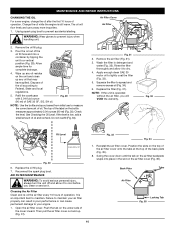
... AIR FILTER MAINTENANCE
WARNING: To avoid serious personal injury, always turn the unit off and allow it . Reinstall the air filter...a small amount of operation. WARNING: Wear gloves to spread and remove excess oil (Fig. 34). 6.
Rinse the filter thoroughly and allow...permanent damage to prevent accidental starting. Tab
Fig. 31
2. Replace the filter (Fig. 31).
The oil will VOID the ...
Operation Manual - Page 11

... smoothly. Disconnect the spark plug wire.
3. socket counterclockwise.
4. Clean dirt from the cylinder head by an authorized service dealer. If the engine stops, insert a small phillips in the spark...
3.
If you turn at a time (as top dead center). Remove the engine cover (Fig. 38). View Of The Rear Engine Cover
Remove Screws
Remove Screws
Fig. 38
5. Remove the rocker arm ...
Operation Manual - Page 12

... nut using a torque wrench torque to:
WARNING: Do not sand blast, scrape or clean electrodes. See Replacing the
Spark Plug. 11. Tighten screws. Remove the spark plug from the cylinder head by turning a 5/8 in . (0.655 mm.)
4. socket counterclockwise.
0.025 in . If using a 5/16 inch (8 mm) wrench or nut driver (Fig. 40). • To increase...
Operation Manual - Page 13

...T-20 bit and a T-25 bit, remove the screws attaching the spark arrestor cover to Changing the Oil. WARNING: To avoid serious personal injury, always turn your unit off any loose or damaged parts...such as kerosene, can damage plastic housing or handle. Remove the spark arrestor screen from the cylinder before transporting. Repair or replace damaged parts and tighten loose screws, nuts or bolts...
Operation Manual - Page 14

... Dirty air filter Plugged spark arrestor
ACTION Turn On/Off control to ON Fill fuel ...Replace or clean the spark plug Clean or replace spark arrestor
ACTION Stop the engine and clean cutting attachment Refill with new line Replace the inner reel Clean inner reel and outer spool Disassemble, remove...head
ACTION Clean and thoroughly dry the cutting head
If further assistance is required, contact ...
Operation Manual - Page 15

... Mechanism ...SpeedSpool® Line Spool...Bump Line Releaser Line Spool Diameter ...4 inches (101.6 mm) Trimming Line Diameter ...095 inches (2.41 mm) Cutting Path Diameter, Trimmer Head ...17 inches (43.2 cm)
*All specifications are based on the latest product information available at any time without notice.
15 SPECIFICATIONS ENGINE*
Engine Type ...Air...
Operation Manual - Page 17

... in non-warranty maintenance or repair and will be grounds for the warranty period. Any replacement part that part. • The owner will not be charged for diagnostic labor which...is performed at an Authorized Troy-Bilt Service Center. Any warranted part which is scheduled for replacement as the carburetor or fuel-injected system, the ignition system, and catalytic converter. Your ...
Operation Manual - Page 18

...improve the design of any Troy-Bilt product without limitation, expenses incurred for substitute or replacement lawn care services, for transportation or for related expenses, or for products sold or exported ... previously manufactured. This warranty is limited to ninety (90) days from the sales.
Box 361131
Cleveland, OH 44136-0019
18 No product returned directly to the factory will void...
Operation Manual - Page 53

PARTS LIST
REPLACEMENT PARTS - MODELS TB575SS & TB525CS 4-CYCLE GAS TRIMMER
Item 1 2 3 4 5 6 7 8 9 10 11 12 13 14 15 16 17 18 19 20 21 22 23 24 25 26 ...
Operation Manual - Page 54
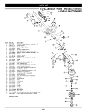
PARTS LIST
REPLACEMENT PARTS - MODELS TB575SS 4-CYCLE GAS TRIMMER
1
4 1... Clamp Assembly (includes 19) 19 791-145569 Anti-Rotation Screw 20 753-05269 Gear Box Assembly (includes 24 & 25) 21 791-180547 Shield Mounting Hardware 22 753-...Large Spring 35 791-181467 Foam Seal 36 791-181468B Bump Head Knob Assembly (includes 34 & 35) * 753-05268 Cutting Head Assembly (18,19 & 24-36)
* Items Not Shown
...
Operation Manual - Page 55

... 791-181464 Inner Reel 791-181465B Large Spring 791-181467 Foam Seal 791-181468B Bump Head Knob Assembly (includes 34 & 35) 753-04929 Complete Cutting Head Assemly
(includes 17, 20, 21, 24-36)
Optional Accessorie * 791-180120 Replacement Line, 0.095"
* Items Not Shown
7 12 13 14
11 15
17 22
23 21
24...
Parts List - Page 3

4 1
23 56
REPLACEMENT PARTS - MODEL TB575es 4-CYCLE GAS TRIMMER
PPN 41CDT57C966
1
7
8
9
10
11
13
12
Item 1 2 3 4 5 6 7 8...Retaining Nut Lower Drive Shaft Housing Assembly Lower Flexible Drive Shaft Anti-Rotation Screw Gear Box Assembly (includes 16) Shield Mounting Screws Shield Assembly (includes 20) Blade Assembly Cutting Head Assembly
* Items Not Shown
14
19 20
18
16 15 17
21
Issued...
Similar Questions


How To Replace The Starter Rope.
The starter rope of my TB575 EC has come off of the starter housing assembly (spool) and is rapped a...
The starter rope of my TB575 EC has come off of the starter housing assembly (spool) and is rapped a...
(Posted by paparowe62 8 years ago)
Changing Trimmer Head On Troy-bilt Tb6044 Xp
I have a TB6044 XP and want to replace the trimmer head with a Pivotrim hybrid. But cannot remove th...
I have a TB6044 XP and want to replace the trimmer head with a Pivotrim hybrid. But cannot remove th...
(Posted by GCP1 8 years ago)

