Toshiba DVR610 Support Question
Toshiba DVR610 Support Question
Find answers below for this question about Toshiba DVR610 - DVDr/ VCR Combo.Need a Toshiba DVR610 manual? We have 1 online manual for this item!
Question posted by rayhchow on April 9th, 2014
I Knock The Dvd Tray Out Of Place. What To Do?
i knock the dvd tray out of place. what to do?
Current Answers
Related Toshiba DVR610 Manual Pages
Service Manual - Page 1
... green product, use the part(s) described in Japan, Jan. 2008 GREEN When repairing this manual and lead-free solder (*2).
SERVICE MANUAL
FILE NO. 810-200803GR
DVD Video Recorder /Video Cassette Recorder
D-VR610KU
The above model is classified as a green product (*1), as indicated by the underlined serial number.
Service Manual - Page 3
MAIN SECTION
DVD VIDEO RECORDER & VIDEO CASSETTE RECORDER
D-VR610KU
Main Section
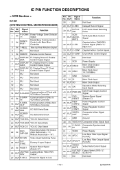
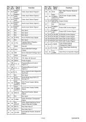
I Specifications I Preparation for Servicing I ...Diagrams 1-12-1 Schematic Diagrams / BOARD's and Test Points 1-13-1 Waveforms 1-14-1 Wiring Diagram < VCR Section 1-15-1 Wiring Diagram < DVD Section 1-15-2 IC Pin Function Descriptions 1-16-1 Lead Identifications 1-17-1 Exploded Views 1-18-1 Mechanical...
Service Manual - Page 4
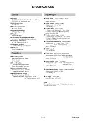
...output Output 1 (rear) Output level: 1 Vp-p (75Ω) Jack: RCA jack S-video input Input 1 (rear) Y (luminance) - Output level: 1 Vp-p (75Ω) C (color) - SPECIFICATIONS
General
System DVD-RW/-R, DVD+RW/+R, DVD-video, CD-DA, CD-RW/-R, VHS cassette tape VCR Video Heads Four heads Power requirements AC120 V, 60 Hz Power consumption 30W(standby: 3.3 W) Weight 9.5 lbs ( 4.3 kg ) Dimensions (width...
Service Manual - Page 13
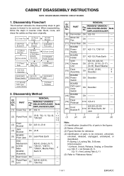
... Front Bracket
[4] Jack Bracket
[5] BOARD Front Jack
[10] Motor DC Fan
[9] Fan Holder
[6] DVD Mechanism & DVD Main BOARD Assembly
[7] Dust Cover
[12] BOARD Power Supply
[11] Panel Rear
[8] Panel Rear ...
[13] BOARD Holder
[15] Deck Assembly
[16] BOARD Power Switch
[17] BOARD DVD open / close Switch
[14] VCR Chassis Unit
[18] BOARD Main
[19] Deck Pedestal
2. Disassembly Method
ID/ LOC. No...
Service Manual - Page 14
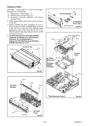
... jumpers as a unit.
(S-1)
[1] Cover Top
(S-1)
(S-5) [4] Jack Bracket
[5] BOARD Front Jack Jack Plate Earth Fig. Replace the DVD Mechanism & DVD Main BOARD Assembly as shown
in Fig. D4 E9KGADC Before installing the Deck Assembly, be sure to break them. 1-1. D9. 4. ... a unit at factory. Therefore, do not disassemble it. Be careful not to
place the pin of LD-SW as shown in Fig.
Service Manual - Page 18

... careful not to damage the gear. 1. Remove the Front Bracket. 4. Pull the tray out manually and remove a disc. Rotate the gear in the direction of the arrow manually as shown below until the tray descends. 7. Remove the DVD Mechanism & DVD Main BOARD Assembly. 5. Unhook two places and detach the Dust Cover. 6.
Remove the Panel Front. 3.
Service Manual - Page 19
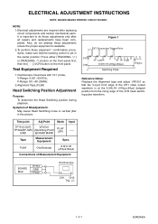
...alignment / confirmation procedures, make sure that the V-sync front edge of the CH1 video output waveform is at the 6.5H±1H (416μs±64μs) delayed... the center position: Press either [TRACKING ] or [TRACKING ] button on the front panel first, then the [ O ] (VCR) button on the front panel.
Syncronize Trigger Point
CH1 CH2
1.0H
0.5H
6.5H±1H (416μs±64μs)...
Service Manual - Page 20
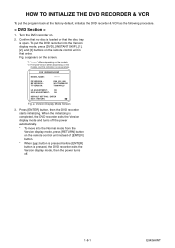
... turns off the power automatically.
* To move into the Version display mode, press [DVD], [INSTANT SKIP], [1], [2], and [3] buttons on the remote control unit in that the disc tray is one example. HOW TO INITIALIZE THE DVD RECORDER & VCR
To put the DVD recorder into the Normal mode from the Version display mode, press [RETURN] button...
Service Manual - Page 21
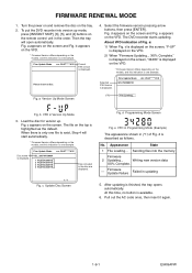
... Mode
3.
Firmware Update Failure
Failed in the disc are displayed.
1 / 1
Fig. Then the tray will start automatically.
* Firmware Version differs depending on the models, and this indication is highlighted as...Complete.
--- To put the DVD recorder into the memory
Firmware
2 Updating... The DVD recorder starts updating. Selected F/W Version is one example. FIRMWARE RENEWAL...
Service Manual - Page 25
...2.90 2.39 1.98 1.61 1.27 0.92 0.51
(V)
KEY-2 IC1501-85
S-INH
-----
Terminal voltage of IC1501? DVD PLAY ----- Check the line between the RS1501 (remote control receiver) and the Pin(5) of IC1501, and replace P1 (...BOARD MCV) if defective
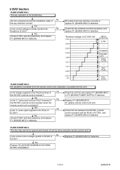
FLOW CHART NO.3 The disc tray cannot be opened and closed. (It can be done using the remote control unit.)
No Is the ...
Service Manual - Page 26

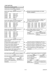
... IC2805 21PIN → CN2201 22PIN VIDEO-C
No Replace P2 (DVD MECHANISM & DVD MAIN BOARD ASSEMBLY).
1-10-5
E9KGATR
IC2805 IC2805 IC2805 IC2805
8PIN 13PIN
2PIN 10PIN
VIDEO-IN 1 (REAR) Y-IN 1 (REAR) C-IN 1 (REAR) VIDEO-IN 2 (FRONT)
Yes
Are the video signals outputted to the pin(1) of IC2805?
FLOW CHART NO.4 The disc tray cannot be opened and closed...
Service Manual - Page 28
...the disc tray, and playback.
Are the luminance signals outputted to the No COMPONENT OUT terminal (JK2403)? Are the Y, Pb/Cb, Pr/Cr signals outputted to the
No
S-VIDEO OUT terminal...
VIDEO-Y(I/P) VIDEO-Pr/Cr VIDEO-Pb/Cb VIDEO-Y(I ) VIDEO-C
Yes
Are the video signals outputted to
No
the VIDEO OUT terminal (JK2751)?
Replace P2 (DVD MECHANISM & DVD MAIN BOARD ASSEMBLY). Yes Is the video ...
Service Manual - Page 30
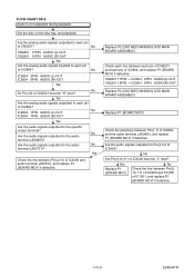
... replace P1 (BOARD MCV) if defective.
Replace P2 (DVD MECHANISM & DVD MAIN BOARD ASSEMBLY).
Set the disc on the disc tray, and playback.
Are the analog audio signals outputted to each... → IC2804 2PIN AUDIO(L)-OUT CN2201 15PIN → IC2804 6PIN AUDIO(R)-OUT
Replace P2 (DVD MECHANISM & DVD MAIN BOARD ASSEMBLY). No Are Pin(9,10,11) of CN2201 become "L" level?
Yes
Are ...
Service Manual - Page 39
....
12
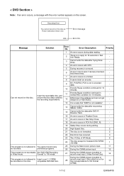
Difference in the address and can not get Stream ID of VR Mode.
6
24
The disc except for finalized DVD-R/RW/ +R/+RW.
1
This program is not recordable Set "DVD-RW Recording
in Video mode.
Message
Solution
Error No.
E35
Error message Error No.
Insert the recordable disc, and
11
Encode Pause condition...
Service Manual - Page 41
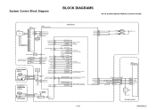
... DIAGRAM
OUTPUT-SELECT OUTPUT-SELECT2
OUTPUT-SELECT2 OUTPUT-SELECT AUDIO-SW1 AUDIO-SW2
TO VIDEO OUTPUT SELECT BLOCK DIAGRAM
TO AUDIO INPUT/OUTPUT SELECT BLOCK DIAGRAM
1-12-1
VCR-LED 94 VCR-LED 95 DVD-LED 96 DVD-LED 97
D1563 D1562
VCR DVD
AL+5V
IC101
MAIN MICRO CONTROLLER
SYS-RESET 44 S-DATA-OUT 16
S-DATA-IN...
Service Manual - Page 45

... BUFFER LPF
Y1
13
MUTE
TO VIDEO
BLOCK
VCR-VIDEO
20 BUFFER
+
DIAGRAM
VIDEO1 8
VIDEO2 10
PB/EE
12
MUTE
(VCR DVD DUBBING)
VCR-VIDEO(DUB)
TO VIDEO BLOCK DIAGRAM
YC
G
G
JK2401 S-VIDEO IN1
REAR JK2804
VIDEO - Video Input Select Block Diagram
NOTE: BOARD MEANS PRINTED CIRCUIT BOARD. IN1
VIDEO-IN1
TO VIDEO OUTPUT SELECT BLOCK DIAGRAM
DVD MAIN BOARD
Q2304 BUFFER
21 BUFFER...
Service Manual - Page 75
...(R)-IN 13
GND
12
AUDIO(L)-IN 11
GND
10
VIDEO-C-OUT 9
GND
8
VIDEO-Y(I/P)-OUT 7
GND
6
VIDEO-Pr/Cr-OUT 5
GND
4
VIDEO-Pb/Cb-OUT 3
GND
2
TO DVD MAIN BOARD CN101
TO DVD MAIN BOARD CN701
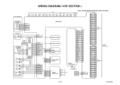
TO WIRING DIAGRAM
VIDEO-Y(I)-OUT 1
1-15-1
E9KGAWI REAR
S-VIDEO S-VIDEO VIDEO
OUT IN
OUT
AUDIO(L) -OUT2
VIDEO- WIRING DIAGRAM< VCR SECTION >
NOTE: BOARD MEANS PRINTED CIRCUIT BOARD.
Service Manual - Page 76
...
14
AUDIO(R)-IN 13
GND
12
AUDIO(L)-IN 11
GND
10
VIDEO-C-OUT 9
GND
8
VIDEO-Y(I/P)-OUT 7
GND
6
VIDEO-Pr/Cr-OUT 5
GND
4
VIDEO-Pb/Cb-OUT 3
GND
2
VIDEO-Y(I)-OUT 1
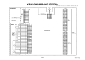
TO BOARD MAIN CN2201
TO WIRING DIAGRAM
1-15-2
E9KGAWID WIRING DIAGRAM< DVD SECTION >
DVD MECHANISM & DVD MAIN BOARD ASSEMBLY
DVD MECHANISM
SPINDLE MOTOR
M
SLED MOTOR
M
CN1001
~
BOARD RELAY
CN1002 1 11...
Service Manual - Page 77
... AFCC
Low Pass Filter Input Signal For AFC
53 OUT AFCLPF
Low Pass Filter Output Signal For AFC
54
OUT
VIDEOMUTE
Video Mute Control Signal
55
OUT
OUTPUTSELECT
Output Select (DVD="L"/ VCR="H")
56 - NU
Not Used
29 OUT D-REC Delayed Record Signal
30
OUT
Hi-Fi-HSW
VCR31 OUT AUDIO- NU
Not Used...
Service Manual - Page 78
...
93
OUT
POWERLED
Power LED Control Signal
94 OUT VCR-LED VCR LED Control Signal
95 OUT VCR-LED VCRLED Control Signal
96 OUT DVD-LED DVD LED Control Signal
97 OUT DVD-LED DVD LED Control Signal
98 OUT C-ROTA
Color Phase Rotary Changeover Signal
99 OUT H-A-SW
Video Head Amp Switching Pulse
100
IN
H-ACOMP
Head...
Similar Questions

Toshiba Sd3109 Dvd Video Player
Why Does My Toshiba 3109 Sd Dvd Video Player Keep Saying Disc Error While Loading
Why Does My Toshiba 3109 Sd Dvd Video Player Keep Saying Disc Error While Loading
(Posted by gloriagrisham57 7 years ago)

Stuck In Standby Mode?
DVR670KU--I have the same problem. My unit has been unplugged for some time---the standby, vcr and d...
DVR670KU--I have the same problem. My unit has been unplugged for some time---the standby, vcr and d...
(Posted by signgod1 8 years ago)

Programming My Toshiba Sd-v296 Tunerless Dvd Vcr Combo Player
how do I program my universal remote to my Toshiba SD-V296 Tunerless DVD VCR Combo Player?
how do I program my universal remote to my Toshiba SD-V296 Tunerless DVD VCR Combo Player?
(Posted by Nathanmartin9 9 years ago)

Toshiba Dvr670 Dvd Recorder/vcr Combo Dvd Player Stop Recording How To Fix
(Posted by kdDE 9 years ago)
