Toshiba DVR610 Support Question
Toshiba DVR610 Support Question
Find answers below for this question about Toshiba DVR610 - DVDr/ VCR Combo.Need a Toshiba DVR610 manual? We have 1 online manual for this item!
Question posted by cwoodw7137 on May 13th, 2013
How Do I Dub A Vhs To Dvd Disc
how do i dub from tape to disc
Current Answers
Related Toshiba DVR610 Manual Pages
Service Manual - Page 1
... green product. TOSHIBA CORPORATION 2008
Published in this manual and lead-free solder (*2).
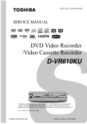
For (*1) and (*2), see the next page. SERVICE MANUAL
FILE NO. 810-200803GR
DVD Video Recorder /Video Cassette Recorder
D-VR610KU
The above model is classified as a green product (*1), as indicated by the underlined serial number.
Service Manual - Page 3
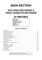
... double-D symbol are trademarks of Dolby Laboratories. MAIN SECTION
DVD VIDEO RECORDER & VIDEO CASSETTE RECORDER
D-VR610KU
Main Section
I Specifications I Preparation for... Schematic Diagrams / BOARD's and Test Points 1-13-1 Waveforms 1-14-1 Wiring Diagram < VCR Section 1-15-1 Wiring Diagram < DVD Section 1-15-2 IC Pin Function Descriptions 1-16-1 Lead Identifications 1-17-1 Exploded Views ...
Service Manual - Page 4
...(video recording) format Video format +VR format Recording discs DVD-Rewritable/-Recordable, DVD+Rewritable/+Recordable
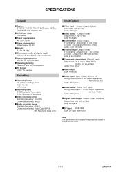
Video ...Video output Output 1 (rear) Output level: 1 Vp-p (75Ω) Jack: RCA jack S-video input Input 1 (rear) Y (luminance) - Output level: 1 Vp-p (75Ω) C (color) - SPECIFICATIONS
General
System DVD-RW/-R, DVD+RW/+R, DVD-video, CD-DA, CD-RW/-R, VHS cassette tape VCR Video...
Service Manual - Page 13
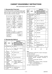
... Cover
[12] BOARD Power Supply
[11] Panel Rear
[8] Panel Rear Unit
[13] BOARD Holder
[15] Deck Assembly
[16] BOARD Power Switch
[17] BOARD DVD open / close Switch
[14] VCR Chassis Unit
[18] BOARD Main
[19] Deck Pedestal
2. PART
REMOVAL
Fig.
REMOVE/*UNHOOK/ UNLOCK/RELEASE/ UNPLUG/DESOLDER
Note
[1] Cover Top D1 7(S-1)
---
1
[2]
Panel Front...
Service Manual - Page 18

3. Remove the Cover Top. 2. Remove the Front Bracket. 4. Remove the DVD Mechanism & DVD Main BOARD Assembly. 5. Pull the tray out manually and remove a disc. Unhook two places and detach the Dust Cover. 6. Rotate the gear in the direction of the arrow manually as shown below until the tray descends. 7.
...
Service Manual - Page 20
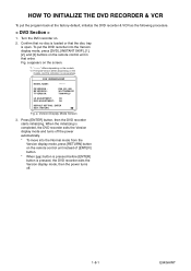
... power automatically.
* To move into the Version display mode, press [DVD], [INSTANT SKIP], [1], [2], and [3] buttons on the remote control unit in that the disc tray is open. To put the program back at the factory-default, initialize the DVD recorder & VCR as the following procedure.
< DVD Section >
1. a appears on the screen.
*1: "*******" differs depending on the...
Service Manual - Page 25
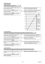
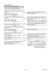
... the Pin(5) of IC1501, and replace P1 (BOARD MCV) if defective
FLOW CHART NO.3 The disc tray cannot be opened and closed. (It can be done using the remote control unit.)
No Is... operation is possible from the remote control unit. (Operation is not functioning.
Terminal voltage of
IC1501?
DUBBING DVD REC /OTR
OPEN/ CLOSE
----- Yes
No
Is the "L" pulse signal supplied to the Pin(5) of...
Service Manual - Page 26

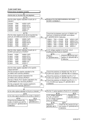
... 3PIN 1PIN 9PIN
VIDEO-Y(I/P) VIDEO-Pr/Cr VIDEO-Pb/Cb VIDEO-Y(I) VIDEO-C
Yes Continued to each pin of CN2201?
FLOW CHART NO.4 The disc tray cannot be opened and closed. [No Disc] indicated. FLOW CHART NO.5 VIDEO E-E does not appear normally.
Yes
No
Replace
Check P-ON+5V line and
P1 (BOARD MCV). Replace P2 (DVD MECHANISM & DVD MAIN BOARD ASSEMBLY...
Service Manual - Page 28
... P2 (DVD MECHANISM & DVD MAIN BOARD ASSEMBLY). Check the line between the emitter of IC2405 and replace P1 (BOARD MCV) if defective. CN2201 7PIN → IC2405 CN2201 5PIN → IC2405 CN2201 3PIN → IC2405 CN2201 1PIN → IC2404 CN2201 9PIN → IC2404
3PIN 8PIN 6PIN 3PIN 1PIN
VIDEO-Y(I/P) VIDEO-Pr/Cr VIDEO-Pb/Cb VIDEO-Y(I ) VIDEO-C
Yes...
Service Manual - Page 30
...P1 (BOARD MCV) if defective. Set the disc on the disc tray, and playback.
No
Check the line ...between Pin(1,7) of IC2406 become "H" level?
No
Are the audio signals outputted to the specific
output terminal? CN2201 17PIN → IC2804 2PIN AUDIO(L)-OUT CN2201 15PIN → IC2804 6PIN AUDIO(R)-OUT
Replace P2 (DVD MECHANISM & DVD...
Service Manual - Page 39
... for 10 minutes.
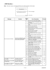
- Recording Error You cannot record on this disc. E35
Error message Error No. Can not record on this disc.
Insert the recordable disc, and
11
Encode Pause condition continued in Video mode.
compatible DVD-RW disc.
Message
Solution
Error No.
ensure the disc status satisfies the recording requirements.
12
Difference in the address and...
Service Manual - Page 40
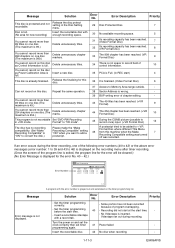
... mode. Delete unnecessary titles.
(The maximum is 99.)
31
Its recording capacity has been reached. (Video Format Disc)
7
32
Its recording capacity has been reached. (VR Format Disc)
8
You cannot record more than 254 chapters on one disc.(The maximum is 254.)
Delete unnecessary chapter marks.
44
The 254 chapter has been reached. (+VR...
Service Manual - Page 41
...93 POWER-LED
BOARD DVD OPEN/CLOSE SWITCH
AL+5V
AUDIO-SW1 61 AUDIO-SW2 60
SW1617
DUBBING CN2210
1 DUBBING-SW
SW1615
2 OPEN/CLOSE-SW
OPEN/CLOSE
CN2209 1 2
TP502 S-INH
KEY SWITCH (DVD)
85 KEY- 2
...AUDIO-SW1 AUDIO-SW2
TO VIDEO OUTPUT SELECT BLOCK DIAGRAM
TO AUDIO INPUT/OUTPUT SELECT BLOCK DIAGRAM
1-12-1
VCR-LED 94 VCR-LED 95 DVD-LED 96 DVD-LED 97
D1563 D1562
VCR DVD
AL+5V
IC101
MAIN ...
Service Manual - Page 45

... SIGNAL PROCESS BLOCK DIAGRAM
VIDEO-Y/CVBS VIDEO-C
CN701
CN2201
20 VIDEO-Y/CVBS-IN 20 22 VIDEO-C-IN 22
Q2305 BUFFER
IC2805 (INPUT SELECT) 19 BUFFER LPF
Y1
13
MUTE
TO VIDEO
BLOCK
VCR-VIDEO
20 BUFFER
+
DIAGRAM
VIDEO1 8
VIDEO2 10
PB/EE
12
MUTE
(VCR DVD DUBBING)
VCR-VIDEO(DUB)
TO VIDEO BLOCK DIAGRAM
YC
G
G
JK2401 S-VIDEO IN1
REAR JK2804
VIDEO - Video Input Select Block...
Service Manual - Page 48

...
Q2804 DRIVE
Q2806 MUTE-ON
JK2805 (REAR)
AUDIO(L) -OUT1
Q2805 MUTE-ON
AUDIO(R) -OUT1
VCR PB (VCR DVD DUBBING)
IC2803 (OP AMP)
1
OP AMP
2
7
OP AMP
6
IC2801 (INPUT SELECT)
(L-CH)
EE
1...4
IN2
5
(R-CH)
EE
12
13
IN1
11
IN2
14
DVD PB (DVD VCR DUBBING)
IC2101 (SW) 13
14 12 3
4 5
SW CTL 9 10 11
DVD-AUDIO(L) DVD-AUDIO(R)
LINE(L)-IN LINE(R)-IN LINE(L)-OUT LINE(R)-OUT
TO Hi-Fi...
Service Manual - Page 49
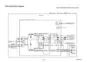
...AMP)
BOARD MAIN
NOTE: BOARD MEANS PRINTED CIRCUIT BOARD. PB AUDIO SIGNAL
REC AUDIO SIGNAL
DVD AUDIO SIGNAL
Mode : SP/REC
SERIAL
DATA
37
DECODER
38
IIC-BUS SDA IIC-BUS ... BLOCK
N-A-OUT
6
DIAGRAM
LINE(R)-IN
TO AUDIO LINE(L)-IN
7
INPUT
/OUTPUT SELECT BLOCK
DVD-AUDIO(L) DVD-AUDIO(R)
9
DIAGRAM DVD PB
(DVD VCR DUBBING)
R-CH INSEL 48 47
NOR SW
L-CH
13 14
INSEL
R-CH PNR
P
SW...
Service Manual - Page 75
...(R)-IN 13
GND
12
AUDIO(L)-IN 11
GND
10
VIDEO-C-OUT 9
GND
8
VIDEO-Y(I/P)-OUT 7
GND
6
VIDEO-Pr/Cr-OUT 5
GND
4
VIDEO-Pb/Cb-OUT 3
GND
2
TO DVD MAIN BOARD CN101
TO DVD MAIN BOARD CN701
TO WIRING DIAGRAM
VIDEO-Y(I)-OUT 1
1-15-1
E9KGAWI
REAR
S-VIDEO S-VIDEO VIDEO
OUT IN
OUT
AUDIO(L) -OUT2
VIDEO-
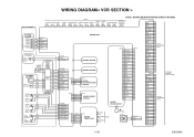
WIRING DIAGRAM< VCR SECTION >
NOTE: BOARD MEANS PRINTED CIRCUIT BOARD.
Service Manual - Page 76
... 6 NU 7 VH(-) 8 HW(-) 9 HW(+) 10 HV(-) 11 HV(+) 12 HU(-) 13 HU(+) 14 VCC 15 U 16 V 17 W
CN301
17 16 15 14 13 12 11 10 9 8 7 6 5 4 3 2 1
PICKUP
FOCUS ACTUATOR
TRACKING ACTUATOR
TILT ACTUATOR
DVD-LD CD-LD
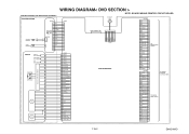
DVD/CD LASER DIODE DRIVE...RESET 27
SUB-SCLK 26
GND
25
GND
24
GND
23
VIDEO-C-IN 22
GND
21
VIDEO-Y/CVBS-IN 20
AUDIO+5V 19
DVD-AUDIO-MUTE 18
AUDIO(L)-OUT 17
GND
16
AUDIO(R)-OUT ...
Service Manual - Page 77
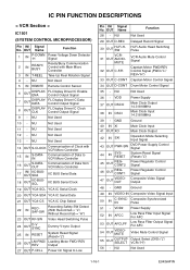
...OUT
VIDEOMUTE
Video Mute Control Signal
55
OUT
OUTPUTSELECT
Output Select (DVD="L"/ VCR="H")
56 - NU
Not Used
11 - MUTE
32 OUT C-F/R
Hi-Fi Audio Head Switching Pulse
VCR Audio Mute...
Power Regulator Control Signal
46
OUT
REGCONT1
Power Regulator Control Signal
47
OUT
VIDEOOUT
Composite Video Signal Output
48 - NU
Not Used
13 - OUT Name
Function
1
IN
P-DOWN...
Service Manual - Page 78
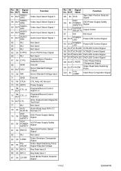
... Voltage Input
71 - NU
Not Used
83 IN V-ENV
84
IN
PGDELAY
Video Envelope Comparator Signal
Video Head Switching Pulse Signal Adjusted Voltage
85 IN KEY-2 Key Data Input 2
...Audio Mode Input HiFi="L"/ Normal="H"
79
IN
DVD POWERSAFETY
DVD Power Supply Safety Signal
80
IN
VCR POWERSAFETY
VCR Power Supply Safety Signal
81 IN END-S
Tape End Position Detect Signal
82 - Output ...
Similar Questions

Toshiba Sd3109 Dvd Video Player
Why Does My Toshiba 3109 Sd Dvd Video Player Keep Saying Disc Error While Loading
Why Does My Toshiba 3109 Sd Dvd Video Player Keep Saying Disc Error While Loading
(Posted by gloriagrisham57 7 years ago)

Stuck In Standby Mode?
DVR670KU--I have the same problem. My unit has been unplugged for some time---the standby, vcr and d...
DVR670KU--I have the same problem. My unit has been unplugged for some time---the standby, vcr and d...
(Posted by signgod1 8 years ago)

Programming My Toshiba Sd-v296 Tunerless Dvd Vcr Combo Player
how do I program my universal remote to my Toshiba SD-V296 Tunerless DVD VCR Combo Player?
how do I program my universal remote to my Toshiba SD-V296 Tunerless DVD VCR Combo Player?
(Posted by Nathanmartin9 9 years ago)

I Knock The Dvd Tray Out Of Place. What To Do?
i knock the dvd tray out of place. what to do?
i knock the dvd tray out of place. what to do?
(Posted by rayhchow 10 years ago)

Toshiba Vhs Dvd Combo Won't Play Vhs Sd-v296
(Posted by kaka1crda 10 years ago)