Toshiba DVR610 Support Question
Toshiba DVR610 Support Question
Find answers below for this question about Toshiba DVR610 - DVDr/ VCR Combo.Need a Toshiba DVR610 manual? We have 1 online manual for this item!
Question posted by signgod1 on March 26th, 2016
Stuck In Standby Mode?
DVR670KU--I have the same problem. My unit has been unplugged for some time---the standby, vcr and dvd lights are all flashing and the unit will not respond to anything. I see the answer of resetting to factory default but the remote commands do not cause any reaction from the machine.
Current Answers
Answer #1: Posted by waelsaidani1 on March 27th, 2016 9:06 AM
waelsaidani1

Member since:
May 12th, 2013 Points: 19,501,797

Member since:
May 12th, 2013 Points: 19,501,797
unplug the AC Adaptor from the laptop, remove the battery, then press the power button down and hold it down for 30 seconds. Now replace the battery and see if it powers up. If it doesn't repeat the process but this time only plug the AC Adapter back in without the battery and try it. If it still doesn't power up, repeat the process but with both the battery and AC plugged in when you power it up.
Related Toshiba DVR610 Manual Pages
Service Manual - Page 3
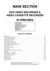
...the double-D symbol are trademarks of Dolby Laboratories. MAIN SECTION
DVD VIDEO RECORDER & VIDEO CASSETTE RECORDER
D-VR610KU
Main Section
I Specifications I Preparation for... Disassembly Instructions 1-6-1 Electrical Adjustment Instructions 1-7-1 How to Initialize the DVD Recorder & VCR 1-8-1 Firmware Renewal Mode 1-9-1 Troubleshooting 1-10-1 Function Indicator Symbols 1-11-1 Block Diagrams...
Service Manual - Page 4
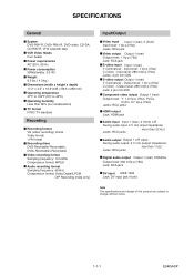
...) - Input level: 286 mVp-p (75Ω) Jacks: 4 pin mini DIN S-video output Output 1 (rear) Y (luminance) - SPECIFICATIONS
General
System DVD-RW/-R, DVD+RW/+R, DVD-video, CD-DA, CD-RW/-R, VHS cassette tape VCR Video Heads Four heads Power requirements AC120 V, 60 Hz Power consumption 30W(standby: 3.3 W) Weight 9.5 lbs ( 4.3 kg ) Dimensions (width x height x depth) 17.2" x 4.0" x 10.6"(435...
Service Manual - Page 12
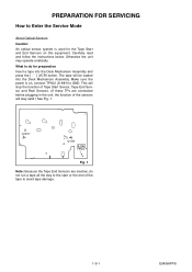
...Because the Tape End Sensors are connected before plugging in the unit, the function of the tape to avoid tape damage.
1-5-1
E9KGAPFS Otherwise the unit may operate erratically. Make sure the power is used for ... Assembly and press the [ O ] (VCR) button.
PREPARATION FOR SERVICING
How to Enter the Service Mode
About Optical Sensors
Caution: An optical sensor system is on this equipment...
Service Manual - Page 19
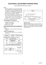
...] button on the front panel first, then the [ O ] (VCR) button on the front panel. Syncronize Trigger Point
CH1 CH2
1.0H
...μs±64μs)
Connections of the CH1 video output waveform is available. 2.To perform these adjustments...TP302
Oscilloscope
CH1 CH2 Trig. (+)
1-7-1
E9KGAEA
Test point
Adj.Point
Mode Input
TP751(V-OUT)
VR1501
TP302(RF-SW) (Switching Point)
GND...
Service Manual - Page 20
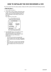
... starts initializing. HOW TO INITIALIZE THE DVD RECORDER & VCR
To put the DVD recorder into the Normal mode from the Version display mode, press [RETURN] button on the remote control unit instead of [ENTER] button.
* When [ ] button is pressed before [ENTER] button is pressed, the DVD recorder exits the Version display mode, then the power turns off the...
Service Manual - Page 36
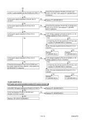
...
Replace P1 (BOARD MCV).
Is the "H" pulse inputted into Pin(3,13) of IC1451? FLOW CHART NO.12 Hi-Fi audio can not be recorded normally. (E-E mode is normal.)
No Is the REC FM signal outputted to Pin(78, 80) of IC1451?
Yes
Is the audio signal outputted to Pin(26) of...
Service Manual - Page 37
...80) of IC1301? FLOW CHART NO.15 Audio can not be playbacked normally in the linear audio mode. (E-E mode is normal.)
Yes Is the audio signal supplied to Pin(10) of IC1301, and replace P1 ... 1B1 (DECK ASSEMBLY). FLOW CHART NO.14 Audio can not be recorded normally in the linear audio mode. (E-E mode is normal.)
No Is the audio signal inputted into to Pin(9) of the ACE head assembly.
...
Service Manual - Page 38
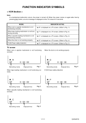
FUNCTION INDICATOR SYMBOLS
< VCR Section >
Note: If a mechanical malfunction occurs, the power is ...capstan mechanism is not functioning correctly
"A R" is not functioning correctly
A P SP
0 : 00 : 00
Recording mode
Elapsed time
Fig. 5
A C SP
0 : 00 : 00
Recording mode
Elapsed time
Fig. 3
1-11-1
E9KGAFIS "A T" is displayed on a TV screen. (Refer to Fig. 2.) tioning correctly
...
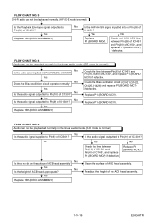
Service Manual - Page 39
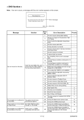
...of RDI/VIDEO.
-
13 It is a reply that "ATAPI is not readable."
-
14
Cannot write the data after recovering SMALL VMGI.
-
15
Cannot write the data after DVD-R Reverse Track...Unit Ready.
-
3
Cannot write the data after trying three times.
-
4 An error occurs with the error number appears on this disc. Insert the recordable disc, and
11
Encode Pause condition continued in Video mode...
Service Manual - Page 40
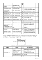
... the finalizing for this disc.
36 It is finalized. (Video Format Disc)
6
37 Access to add a postscript. Can...error number is Full. (in +VR mode. Delete unnecessary titles.
34
There is not recordable Set "DVD-RW Recording
in REC start)
4
full....not start at the start time.
40 - Message
Solution
Error No.
Set the timer programming before the start time.
-
-
A postscript tried...
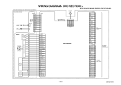
Service Manual - Page 41
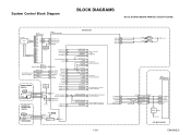
... OUTPUT-SELECT2
OUTPUT-SELECT2 OUTPUT-SELECT AUDIO-SW1 AUDIO-SW2
TO VIDEO OUTPUT SELECT BLOCK DIAGRAM
TO AUDIO INPUT/OUTPUT SELECT BLOCK DIAGRAM
1-12-1
VCR-LED 94 VCR-LED 95 DVD-LED 96 DVD-LED 97
D1563 D1562
VCR DVD
AL+5V
IC101
MAIN MICRO CONTROLLER
SYS-RESET 44 S-DATA-OUT 16
S-DATA-IN 15 S-CLOCK 14
READY...
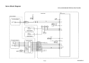
Service Manual - Page 42
...
CAPSTAN MOTOR
CAPSTAN MOTOR
M
MOTOR DRIVE CIRCUIT
BOARD MAIN
IC1501 (SERVO CONTROL)
TP506 TP505 TP507 ST-S T-REEL END-S
Q1506 T-REEL
TP513 CTL
SW1512 AL+5V(1) MODE-SW
76 CTL 74 CTL(+) 75 CTL(-)
87 LD-SW
88 ST-S 81 END-S 3 T-REEL
CN1502
1 AL+12V(1) 2 P-ON+5V(1) 3 C-FG 4 C-F/R 5 C-CONT 6 GND 7 LM-FWD...
Service Manual - Page 45

... VIDEO SIGNAL
TO DIGITAL SIGNAL PROCESS BLOCK DIAGRAM
VIDEO-Y/CVBS VIDEO-C
CN701
CN2201
20 VIDEO-Y/CVBS-IN 20 22 VIDEO-C-IN 22
Q2305 BUFFER
IC2805 (INPUT SELECT) 19 BUFFER LPF
Y1
13
MUTE
TO VIDEO
BLOCK
VCR-VIDEO
20 BUFFER
+
DIAGRAM
VIDEO1 8
VIDEO2 10
PB/EE
12
MUTE
(VCR DVD DUBBING)
VCR-VIDEO(DUB)
TO VIDEO BLOCK DIAGRAM
YC
G
G
JK2401 S-VIDEO IN1
REAR JK2804
VIDEO...
Service Manual - Page 48

...
AUDIO(R) -OUT2
9 10 11
OUTPUT-SELECT TO SYSTEM CONTROL BLOCK DIAGRAM
Q2804 DRIVE
Q2806 MUTE-ON
JK2805 (REAR)
AUDIO(L) -OUT1
Q2805 MUTE-ON
AUDIO(R) -OUT1
VCR PB (VCR DVD DUBBING)
IC2803 (OP AMP)
1
OP AMP
2
7
OP AMP
6
IC2801 (INPUT SELECT)
(L-CH)
EE
1
3
IN1
4
IN2
5
(R-CH)
EE
12
13
IN1
11
IN2
14...
Service Manual - Page 49
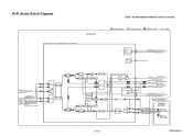
... AUDIO SIGNAL
DVD AUDIO SIGNAL
Mode : SP/REC
SERIAL
DATA
37
DECODER
38
IIC-BUS SDA IIC-BUS SCL
TO SYSTEM CONTROL BLOCK DIAGRAM
RIPPLE
FILTER
54
P-ON+9V
69
71
TO AUDIO BLOCK
N-A-OUT
6
DIAGRAM
LINE(R)-IN
TO AUDIO LINE(L)-IN
7
INPUT
/OUTPUT SELECT BLOCK
DVD-AUDIO(L) DVD-AUDIO(R)
9
DIAGRAM DVD PB
(DVD VCR DUBBING)
R-CH...
Service Manual - Page 52
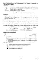
...mode on the schematics are as shown below:
< DVD Section >
1 2 5.0
3 5.0
PLAY mode REC mode
(2.5)
The same voltage for
both PLAY & STOP modes
Indicates that the voltage is not consistent here.
< VCR Section >
123
PLAY mode
5.0
5.0
REC mode
(2.5) DVD mode
The same voltage for
< >
both PLAY, REC & DVD... ONLY WITH THE SAME TYPE FUSE. Unit: Volts
5. Ce symbole represente un ...
Service Manual - Page 75
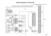
... 6
GND
5
GND
4
SPDIF
3
GND
2
1V2CONT 1
CN2201
SUB-RXD
30
RDY
29
SUB-TXD
28
SYS-RESET 27
SUB-SCLK 26
GND
25
GND
24
GND
23
VIDEO-C-IN 22
GND
21
VIDEO-Y/CVBS-IN 20
AUDIO+5V 19
DVD-AUDIO-MUTE 18
AUDIO(L)-OUT 17
GND
16
AUDIO(R)-OUT 15
GND
14
AUDIO(R)-IN...
Service Manual - Page 76
...
2
1V2CONT 1
TO BOARD MAIN CN2204
CN701
SUB-RXD
30
RDY
29
SUB-TXD
28
SYS-RESET 27
SUB-SCLK 26
GND
25
GND
24
GND
23
VIDEO-C-IN 22
GND
21
VIDEO-Y/CVBS-IN 20
AUDIO+5V 19
DVD-AUDIO-MUTE 18
AUDIO(L)-OUT 17
GND
16
AUDIO(R)-OUT 15
GND
14
AUDIO(R)-IN...
Service Manual - Page 77
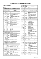
...-SW
DVD Power Supply Control Signal
44
IN
SYSRESET
System Reset Signal (Reset="L")
45
OUT
REGCONT2
Power Regulator Control Signal
46
OUT
REGCONT1
Power Regulator Control Signal
47
OUT
VIDEOOUT
Composite Video Signal Output
48 - OUT Name
Function
1
IN
P-DOWN -H
Power Voltage Down Detector Signal
2
IN
READY/ BUSY
Ready/Busy Communication Control with VCR Micro...
Service Manual - Page 78
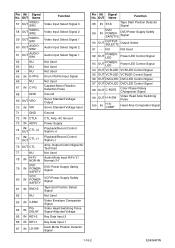
... OUT Name
57
OUT
VIDEOSW3
Function Video Input Select Signal 3
58
OUT
VIDEOSW2
59
OUT
VIDEOSW1
60
OUT
AUDIOSW2
61
OUT
AUDIOSW1
Video Input Select Signal 2 Video Input Select Signal 1 Audio Input ...78
IN
Hi-Fi/ NOR-IN
Audio Mode Input HiFi="L"/ Normal="H"
79
IN
DVD POWERSAFETY
DVD Power Supply Safety Signal
80
IN
VCR POWERSAFETY
VCR Power Supply Safety Signal
81 IN END-S...
Similar Questions

Toshiba Sd3109 Dvd Video Player
Why Does My Toshiba 3109 Sd Dvd Video Player Keep Saying Disc Error While Loading
Why Does My Toshiba 3109 Sd Dvd Video Player Keep Saying Disc Error While Loading
(Posted by gloriagrisham57 7 years ago)

Will A Universal Remote Work With My Toshiba Dvd Video Player Sd-v296ku?
(Posted by noleqdhave0 10 years ago)

How To Connect Toshiba Sdv296 Tv To Cable To Vcr Dvd Combo
(Posted by smDRLAR 10 years ago)


Vcr/dvd Combo
Does this unit record from vhs to dvd on the same unit?
Does this unit record from vhs to dvd on the same unit?
(Posted by beckysallee 12 years ago)