Sony PCS-1 Support Question
Sony PCS-1 Support Question
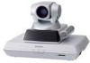
Find answers below for this question about Sony PCS-1 - Video Conferencing Kit.Need a Sony PCS-1 manual? We have 1 online manual for this item!
Current Answers
Related Sony PCS-1 Manual Pages
Operating Instructions - Page 6

...135
Using Audio/Video Signal from the Connected Equipment for a Conference 136
Setting Before Conferencing .... 136
6
Operating the System During a Conference 136
Displaying the Picture on a ...the Cascade Connection via LAN (Up to External Equipment 125 Conducting a Conference Without the Picture - Voice Meeting 126 Controlling the Remote System With the Tone Signal - Communication Submenu...
Operating Instructions - Page 7

... from a Remote
Party 195
Appendix
Location and Function of Parts and Controls 196
PCS-P1/P1P Communication Terminal 196
PCS-C1/C1P Camera Unit ....... 197 PCS-R1 Remote Commander .. 198 PCS-B768 ISDN Unit
(Optional 200 PCS-B384 ISDN Unit
(Optional 200 PCS-DSB1 Data Solution Box
(Optional 201 On Screen Messages 202
Troubleshooting 212
Specifications 216...
Operating Instructions - Page 12

... System.
It contains the following components:
Unit
Description
PCS-P1/P1P Communication Contains the video codec, audio codec, echo
Terminal
canceler, network interfaces and system controller.
Basic System Components
The PCS-1/1P Video Communication System is composed of the camera and an integrated microphone.
PCS-AC195 AC adaptor
Supplies power to operate the Communication...
Operating Instructions - Page 15

Chapter 1: Installation and Preparation
System Configuration
The PCS-1/1P Video Communication System has various system configuration capabilities using the basic components and optional equipment. System configuration
1 PCS-P1/P1P Communication Terminal 2 PCS-C1/C1P Camera Unit 3 PCS-R1 Remote Commander 4 TV monitor (not supplied)
ON LINE POWER LAN ALERT
ON LINE POWER LAN ALERT
System ...
Operating Instructions - Page 16

...PCS-C1/C1P Camera Unit
3 PCS-R1 Remote Commander
4 TV monitor (not supplied)
ON LINE POWER LAN ALERT
* 5 PCS-B384 or PCS-B768 ISDN Unit (not supplied)
*
ON LINE POWER LAN ALERT
* The illustration shows an example using the PCS-B768). Each ISDN line is required to use with the PCS...a single communication, the faster speeds and higher-quality picture you : • To hold a point-to-point...
Operating Instructions - Page 17

...8226; To pick up a large number of participants' voices using up to install the optional PCS-323M1 H.323 MCU software. System configuration
ON LINE POWER LAN ALERT
ON LINE POWER LAN ... ALERT
ON LINE POWER LAN ALERT
1 PCS-P1/P1P Communication Terminal 2 PCS-C1/C1P Camera Unit 3 PCS-R1 Remote Commander 4 TV monitor (not supplied) 5 PCS-323M1 H.323 MCU software (not supplied)
System Configuration...
Operating Instructions - Page 18

... LINE POWER LAN ALERT
ON LINE POWER LAN ALERT ON LINE POWER LAN ALERT
1 PCS-P1/P1P Communication Terminal 2 PCS-C1/C1P Camera Unit 3 PCS-R1 Remote Commander 4 TV monitor (not supplied) 5 PCS-320M1 H.320 MCU software (not supplied) 6 PCS-B384 or PCS-B768 ISDN Unit (not supplied)
The illustration shows an example using up a large number...
Operating Instructions - Page 19

...320 MCU software (for ISDN) enables conduct of participants' voices using the PCS-B768 ISDN Unit. System configuration
LAN*
ON LINE POWER LAN ALERT
ON LINE...ALERT
1 PCS-P1/P1P Communication Terminal 2 PCS-C1/C1P Camera Unit 3 PCS-R1 Remote Commander 4 TV monitor (not supplied) 5 PCS-323M1 H.323 MCU software (not supplied) 6 PCS-320M1 H.320 MCU software (not supplied) 7 PCS-B384 or PCS-B768 ISDN...
Operating Instructions - Page 20

... LAN ALERT
ON LINE POWER LAN ALERT
ON LINE POWER LAN ALERT
1 PCS-P1/P1P Communication Terminal 2 PCS-C1/C1P Camera Unit 3 PCS-R1 Remote Commander 4 TV monitor (not supplied) 5 PCS-323M1 H.323 MCU software (not supplied) 6 PCS-DSB1 Data Solution Box (not supplied) 7 PCS-A1 Microphone (not supplied)
20 System Configuration
System Configuration via a LAN for...
Operating Instructions - Page 21

... LINE POWER LAN ALERT ON LINE POWER LAN ALERT
1 PCS-P1/P1P Communication Terminal 2 PCS-C1/C1P Camera Unit 3 PCS-R1 Remote Commander 4 TV monitor (not supplied) 5 PCS-320M1 H.320 MCU software (not supplied) 6 PCS-B384 or PCS-B768 ISDN Unit (not supplied) 7 PCS-DSB1 Data Solution Box (not supplied) 8 PCS-A1 Microphone (not supplied)
The illustration shows an...
Operating Instructions - Page 22

... the 100BASE-TX/10BASE-T connector to a network that
applies an excess voltage via a LAN
PCS-C1/C1P Camera Unit
TERMINAL
VISCA OUT
to TERMINAL
PCS-P1/P1P Communication Terminal
Camera cable* to CAMERA UNIT
AUDIO OUT
AUX1-VIDEO IN-AUX2 AUDIO IN
(MIXED)
VIDEO OUT
AUX
MAIN- Notes • Be sure to a wall outlet
22 System Connections
Operating Instructions - Page 23

...; Used with the ISDN Unit)
ISDN Unit**
to TERMINAL
PCS-B384
1
2
3
S-video connecting cable*
PCS-B768
1
2
3
4
5
6
to S-video input
TV monitor**
to ISDN 1-3
to ISDN 1-6
ISDN modular cable**
* supplied ** not supplied
to audio input
to CAMERA UNIT
AUDIO OUT
AUX1-VIDEO IN-AUX2 AUDIO IN
(MIXED)
VIDEO OUT
AUX
MAIN- While the upgrading message is displayed on...
Operating Instructions - Page 118

... this case, wait until the echo disappears.
118 Using Multiple Microphones TERMINAL
VISCA OUT
AUDIO OUT
AUX1-VIDEO IN-AUX2 AUDIO IN
(MIXED)
VIDEO OUT
AUX
MAIN- In this case the built-in the PCS-C1/C1P Camera Unit is supplied to the microphones from equipment that may be used to participate in a quiet...
Operating Instructions - Page 133

... cause malfunction of the system.
Chapter 5: Data Conference
Connection Example Using the Data Solution Box 133 PCS-C1/C1P Camera Unit
PCS-P1/P1P Communication Terminal
ON LINE POWER LAN ALERT
Interface cable (supplied with to DSB the PCS-DSB1)
Front
RGB IN A
to RGB IN A D-sub 15-pin
cable (not supplied)
Computer
Computer...
Operating Instructions - Page 134

... connected to the Data Solution Box is supplied from the PCS-P1/P1P
Communication Terminal with a connection described above. • Connect a projector, etc. The received computer picture can be output from these connectors. In this case, try to suppress any echo in a conferencing room. Notes on the connection of conference room. to the...
Operating Instructions - Page 136

...to select that from the Connected Equipment for a Conference
Setting Before Conferencing
To use a projector, etc.
To select the picture from the computer connected to the RGB IN A connector, press...System During a Conference
To select a picture from a computer connected to the Data Solution Box
When using the Remote Commander
1 Press the VIDEO INPUT SELECT button on the Remote Commander...
Operating Instructions - Page 197

... uses the dual monitor mode. Connect to conduct a conference via a LAN or using the category 5 cable.
PCS-C1/C1P Camera Unit
Front 1
3
4
2
5
Rear
Bottom
TERMINAL
VISCA OUT
67
8
Location and Function of Parts and Controls 197
l VIDEO OUT MONITOR SUB connector (mini DIN 4-pin) Connect to the IR OUT 2 jack. n IR OUT 1/2 jacks...
Operating Instructions - Page 199

...to the next layer.
Deletes a line when used for camera angle adjustment. d PinP (BACK SPACE) button Displays a window picture when pressed during communication. f RETURN button Used to ...Each time you entered last.
o HELP button Used to reduce the picture
k VIDEO INPUT SELECT (SYMBOL) button Selects the video input signal.
Each time you press this button, the location of...
Operating Instructions - Page 216

...) (when using LAN)
Network
Multiplexing Video, audio, data
Frame format H.221 ...camera control H.281 (compliant with ITU-T Recommendation)
Data transfer T.120 (compliant with ITU-T Recommendations H.320 and H.323. D (4CIF) H.263 (special format of connection between
both color systems
Still Picture
Pixels Encoding
704 pixels × 480 lines (PCS-P1) 704 pixels × 576 lines (PCS...
Operating Instructions - Page 217

...(2)
IR repeater (2)
Camera cable (0.25 m, 0.8 ft) (1)
S-video connecting cable (1.5 m,
4.9 ft) (1)
Audio connecting cable (1 m, 3.3
ft) (1)
AC adaptor PCS-AC195 (1)
Power cord (1)
21-pin adaptor (1) (PCS-P1P only)
Velcro (3 for the Camera Unit, 2
for the Communication
Terminal)
CD-ROM (1)
Operation guide (1)
Warranty booklet (1)
PCS-C1/C1P Camera Unit
Video signal
NTSC color, EIA...
Similar Questions

Is Sony Pcs-xg80 Compatible With Other Brands Video Conference Device
Please tell me if one side sony PCS-XG80 video conference and other place is other brands video conf...
Please tell me if one side sony PCS-XG80 video conference and other place is other brands video conf...
(Posted by qrijaybajracharya 11 years ago)

Difference Betweeen Sony Pcs-xg80 And Sony Pcs-xg80s
WHAT IS THE DIFFERENCE BETWEEEN SONY PCS-XG80 AND SONY PCS-XG80S, TECHNICALLY AND COMMERCIALLY
WHAT IS THE DIFFERENCE BETWEEEN SONY PCS-XG80 AND SONY PCS-XG80S, TECHNICALLY AND COMMERCIALLY
(Posted by varshneysubodhh 11 years ago)

Buy A Pcs-a1 Microphone Here In Italy, Where ? Or Where To Ask ?
(Posted by mamontanari 12 years ago)

Do You Have Pcs-c1 D-sub Pin Assign
Do you have pcs-c1 D-sub pin assign
Do you have pcs-c1 D-sub pin assign
(Posted by leelee1105 12 years ago)

Sony Pcs-1600p Video Conferencing System Upgrade
Hi I have Sony Conferencing system model PCS-1600P , and i want to upgrade it to work on LAN using ...
Hi I have Sony Conferencing system model PCS-1600P , and i want to upgrade it to work on LAN using ...
(Posted by sameerasmi 12 years ago)