
Sony HCD-D670AV Support Question
Sony HCD-D670AV Support Question
Find answers below for this question about Sony HCD-D670AV - Compact Disk Deck Receiver.Need a Sony HCD-D670AV manual? We have 1 online manual for this item!
Question posted by mjrs49 on September 28th, 2012
Volume Intermittent
The person who posted this question about this Sony product did not include a detailed explanation. Please use the "Request More Information" button to the right if more details would help you to answer this question.
Current Answers
Related Sony HCD-D670AV Manual Pages
Service Manual - Page 1
...
System
compact disc
digital audio system
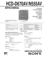
Laser...D670AV, LBT-N555AV. COMPACT DISC DECK RECEIVER
MICROFILM
- 1 - CD SECTION
TAPE DECK SECTION
Model Name Using Similar Mechanism CD Mechanism type Base Unit Type Optical Pick-up Block with no more than 0.9 % total harmonic distortion from Dolby Laboratories Licensing Corporation.
HCD-D670AV/N555AV
SERVICE MANUAL
HCD-D670AV, HCD...
Service Manual - Page 2
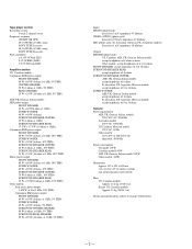
... 40 W (8 ohms, at 1kHz 5% THD) SURROUND REAR SPEAKER 20 W + 20 W (16 ohms, at 1 kHz, 5% THD)
Inputs PHONO (phono jack):
Sensitivity 3 mV, impedance 47 kilohms VIDEO (AUDIO) (phono jack):
Sensitivity 250 mV, impedance 47 kilohms MIC (phone jack): (E, Australian, Mexican, PX, Aregentine models)
Sensitivity 1 mV, impedance 10 kilohms
Outputs PHONES (phone jack...
Service Manual - Page 3
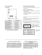
...SCHEMATIC DIAGRAMS AND IN THE PARTS LIST ARE CRITICAL TO SAFE OPERATION. REPLACE THESE COMPONENTS WITH SONY PARTS WHOSE PART NUMBERS APPEAR AS SHOWN IN THIS MANUAL OR IN ...PAR SONY.
- 3 -
The CLASS 1 LASER PRODUCT MARKING is located inside the unit.
MODEL D670AV: US model D670AV: Canadian model N555AV: AEP model N555AV: German model N555AV: Italian model N555AV: UK model N555AV: ...
Service Manual - Page 4
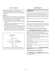
... 0.5 mA (500 microampers). SERVICING NOTE
NOTES ON HANDING THE OPTICAL PICK-UP BLOCK OR BASE UNIT
The laser diode in the following order, K 2 n K 3 n K 4. When the VOLUME knob is easily damaged and should be focused on the disc reflective surface by the charged electrostatic load, etc. J1 n J2 n J3. Press any exposed...
Service Manual - Page 5
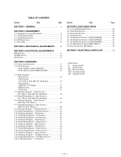
...34
5-5. Tuner Section - (AEP, UK, G, IT Model 38
5-7. CD Panel Section 41 5-9. Deck Section 49 5-13. Power Section 73 5-19. Schematic Diagram - Schematic Diagram - CD Motor Section...Master Control (TMP87CS64YF 19
5-3. Printed Wiring Board - GENERAL 6
SECTION 2. ELECTRICAL ADJUSTMENTS DECK Section 11 TUNER Section 14 CD Section 15
SECTION 5. Block Diagrams • Main...
Service Manual - Page 8

SECTION 2 DISASSEMBLY
Note: Follow the disassembly procedure in the numerical order given. 2-1. TC MECHANISM DECK
6Button (eject-L)
3Three screws (BVTP 2.6X8)
8Main board
4Four screws (BVTP 2.6X8)
5TC mechanism deck 6Button (eject-R)
2Remove the two cassette lids direction of arrow.
- 8 -
1Push the eject button. FRONT PANEL ASSY AND MAIN BOARD
1Remove the connectors...
Service Manual - Page 11
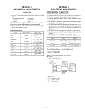
...0 dB
Used for Azimuth Adjustment Tape Speed Adjustment
Level Adjustment
Record/Playback Head Azimuth Adjustment
DECK A DECK B
Note : Perform this
service manual. (As a general rule, playback circuit adjustment ...with a head damagnetizer. 2. Do not use a magnetized screwdriver for both decks. The adjustments should be completed before performing recording circuit adjustment.) 6. The ...
Service Manual - Page 12
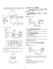
...After the adjustments, apply suitable locking compound to -7.2 dB) level difference between deck A and deck B the beginning of oscilloscope
in playback (REV) mode. 5. Adjust RV652 ...frequency counter
reading becomes 6,000 ± 30 Hz. 4. Adjustment Location : MD board
Playback Level Adjustment DECK A DECK B
Procedure : Mode : Playback (FWD)
test tape P-4-L300 (315Hz, 0dB)
level meter
set ...
Service Manual - Page 13

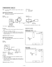
...403 PB level: 47.2 to 53.0 mV (-24.3 to repeat steps 1 and 2. Record Bias Current Adjustment DECK B
Procedure : 1. Mode : record
AF OSC attenuator
VIDEO IN
1) 315Hz 2) 10kHz
50mV (-23.8dB)...the main board to -23.3 dB)
Adjustment Location : main board
Adjustment Location
[MAIN BOARD] (Component Side)
1 3 CN403
RV351 REC LEVEL (R-CH)
RV301 REC LEVEL (L-CH)
Record Level Adjustment Procedure...
Service Manual - Page 14
...the output of SGG so that the input level of the set
Carrier frequency : 98MHz
Modulation
: AUDIO 1kHz, 75kHz
deviation (100%)
Output level
: 25dB (at 10 kHz step)
60 cm
AM ...Tuned
FM Tuned Level
Level Adjustement. Adjustment Location
AEP, UK, G, IT model [TCB BOARD] (Component Side)
IC41
RV41 AM Tuned Level
Adjustment Location : TCB board
FM Tuned Level Adjustment
RV42
Note...
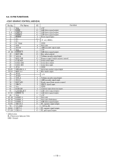
Service Manual - Page 18
....
I Serial clock input. O Key select control.
O Request signal from master control.
O FL grid signal output.
- 18 - O LED drive signal output. I Volume encoder signal input. O Serial data output.
I Key matrix input.
- -
+5V
I Volume encoder signal input. O LED select signal output. O Not used .
GM CLK MG DATA GM DATA MG AVSS SPEANA 4-1 KEY 4-1 AVDD...
Service Manual - Page 20
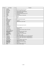
...output. (PLL, Function, Graphic Equalizer)
O Not used . O REC/PB select signal output. O Mute signal for electrical volume. (Not used)
O Not used . O Disc No. O Dolby pro-logic control ourput.
O Not used . O ...I
I
I
I
O PLL latch output.
O Deck A, B select output.
- 20 - O Latch signal digital signal processor. O Not used .
I O
Audio bus in/output. (Not used .
LED drive signal...
Service Manual - Page 21
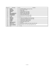
... output (Not used)
O O
ECHO delay level control signal output (Not used .
O Capstan motor control signal output. I Stereo detection signal from tuner. O Latch signal output for deck.
O REC/PB control signal output. O O
Trigger motor control signal output.
O Not used )
- +5V
- 21 - O Capstan motor ON/OFF control signal output. Pin No.
81 82...
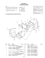
Service Manual - Page 43
...(N555AV:MX)
- 85 - are
seldom required for safety. CABINET AND BALCK PANEL SECTION
The components identified by mark ! No.
4-963-404-21 EMBLEM (5-A), SONY
6
A-4303-502-A TCB BOARD...N555AV:AEP,UK) * 8
A-4303-503-A TCB BOARD, COMPLETE (N555AV:IT,G)
*8
A-4303-510-A TCB BOARD, COMPLETE(D670AV)
*8
A-4303-513-A TCB BOARD, COMPLETE
(N555AV:E,AUS,AR,MX,PX) * 8
*8
A-4303-514-A TCB BOARD,...
Service Manual - Page 46

...:AEP,UK,G,IT,E,AUS,PX,AR)
TRANSFORMER, POWER (N555AV:AEP,UK,G,IT) TRANSFORMER, POWER (D670AV) TRANSFORMER, POWER (N555AV:E,AUS,PX,MX,AR)
- 88 - Replace only with mark ! Description...UK model CNP1601
#1
not supplied 159
#4 not supplied
156 157
D670AV model
CNP1601
not supplied #1
not supplied
158 160 161
The components identified by mark ! Les composants identifiés par une marque...
Service Manual - Page 51

... - 6-9. sont critiques pour la sécurité. Part No.
BASE UNIT SECTION (BU-5BD19)
402 401
rA
#12
403
M101 (including rA)
405
S101
The components identified by mark ! Les composants identifiés par une marque ! No.
* 407 408 M101 M102
Part No. Replace only with mark !
are critical for safety...
Service Manual - Page 52
...la sécurité. Description
Remark Ref. BD
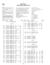
SECTION 7
ELECTRICAL PARTS LIST
Note:
The components identified by reference number, please include the board name.
• Due to standardization, replacements in...anticipated when ordering these items.
• RESISTORS All resistors are in the diagrams or the components used on the set.
• -XX, -X mean standardized parts, so they may ...
Service Manual - Page 63

...
0.039uF 2.2uF 47PF 220PF
5% 50V 20% 50V 5% 50V 10% 50V
*
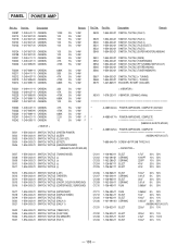
A-4389-610-A PANEL BOARD, COMPLETE (D670AV)
*
A-4389-629-A PANEL BOARD, COMPLETE
(N555AV:AEP,UK,G,IT)
*
A-4389-619-A PANEL BOARD, COMPLETE
(N555AV:E,...126-793-11 ELECT C518 1-126-157-11 ELECT
33uF
20% 35V
10uF
20% 16V
The components identified by mark ! Part No. MD MIC PANEL
Ref. Ne les remplacer que par une...
Service Manual - Page 66
...TACTILE (+ TUNING) 1-554-303-21 SWITCH, TACTILE (- No. TUNING) 1-467-869-11 ENCODER, ROTARY (VOLUME)
R3221 R3222 R3223 R3224 R3231
1-249-411-11 CARBON 1-249-437-11 CARBON 1-247-895-91 CARBON 1-...21 SWITCH, TACTILE (KARAOKEPON/MPX)
(N555AV:E,AUS,PX,MX,AR)
A-4389-604-A POWER AMP BOARD, COMPLETE (D670AV
A-4389-617-A POWER AMP BOARD, COMPLETE N555AV:E,AUS,PX,MX,AR)
A-4389-625-A POWER AMP BOARD, ...
Service Manual - Page 71

...057-09 DIODE LNJ801LPDJA (r REC)
R207 1-249-416-11 CARBON
820
5% 1/4W F
The components identified by mark !
S.
R1460 1-208-602-11 WIREWOUND 0.22
R1461 1-249-417-11 CARBON
...03 DIODE SEL5423E-TP15 (·)(DECK B) 8-719-058-03 DIODE SEL5423E-TP15 (ª)(DECK B) 8-719-058-03 DIODE SEL5423E-TP15 (·)(DECK A) 8-719-058-03 DIODE SEL5423E-TP15 (ª)(DECK A) 8-719-058-03 DIODE ...
Similar Questions

Sony Compact Disc Deck Receiver Model No. Hcd-zx6 Power Light Flashing.
please i need help getting this system working. I paid a lot of money for this system lol
please i need help getting this system working. I paid a lot of money for this system lol
(Posted by true2dan0ne 3 years ago)

Where To Buy A Sony 265 Watt Compact Disc Deck Receiver Hcd-gx450
(Posted by jenkyml 10 years ago)

How Much Sony Compact Disc Deck Receiver, Hcd 541
(Posted by golal 10 years ago)

What Is The Sollution For Fried Compact Disc Deck Reciever?
(Posted by quinonesfrancisca33 12 years ago)
What Is The Value Of The Sony Hcd-lx50 Compact Disk Deck Receiver ?
How much id the Sony HCD-LX50 compact disk deck receiver worth?
How much id the Sony HCD-LX50 compact disk deck receiver worth?
(Posted by Strong 12 years ago)