
Sharp CD-E99 Support Question
Sharp CD-E99 Support Question
Find answers below for this question about Sharp CD-E99.Need a Sharp CD-E99 manual? We have 1 online manual for this item!
Question posted by romeovalmeo on January 28th, 2012
Radio Not Working
just bought 2weeks ago and its a used one and radio not working,everythingelse works fine,no remote no antenna
please help.....thank you
Current Answers
Related Sharp CD-E99 Manual Pages
Service Manual - Page 1

S2316CDE99///
MINI COMPONENT SYSTEM
MODEL CD-E99
CD-E99 Mini Component System consisting of CD-E99 (main unit) and CP-E99 (speaker system).
• In the interests of the CD-E700/CD-E77, This manual, therefore, describes only the changed points from the service manual. CD-E700/CD-E77
Page REMOVING AND REINSTALLING THE MAIN PARTS ...9 ADJUSTMENT ...10 TROUBLESHOOTING ...37 FUNCTION TABLE OF ...
Service Manual - Page 2

...with 1000 ohm per channel into a 120 volt AC outlet. * Using two clip leads, connect a 1.5 kohm, 10 watt resistor paralleled...audio product to the chassis (antenna, metal cabinet, screw heads, knobs and control shafts, escutcheon, etc.) and measure the AC voltage drop across the resistor (See diagram). * Connect the resistor connection to all lead dress to 0.2 milliamp. SPECIFICATIONS
CD-E99...
Service Manual - Page 3

...Indicators 4. FM/AM Loop Antenna Jack 4. Tuning and Time Down Button 9. Extra Bass/Demo Mode Button 14. Volume Control 15. CD or Tape Stop Button 21. CD Track Down or Fast Reverse,...Video/Auxiliary (Audio Signal) Input Jacks 5. Tuning and Time Up Button 8. CD Track Up or Fast Forward, Tape 2 Fast Forward,
Tuner Preset Up Button
1
2 3 4 5 6 7 8 9 10 11
18 19
20 21
CD-E99
12 13 ...
Service Manual - Page 4

CD-E99
CD-E99
Remote control
1. Program Clear Button 4. CD Pause Button 7. CD or Tape Stop Button 8. Tape (1 2) Button 11. Direct Search Buttons 14. Super Tweeters 2. CD Track Down or Fast Reverse,
Tape 2 Rewind Button 6. Extra Bass Button 18. Passive Radiator 5. Power On/Stand-by Button 12. Equalizer Mode Select Button 19. CD Memory Button 5. Tape 2 Record Pause Button ...
Service Manual - Page 5
...so as to keep it lock by front
movement.
CD-E99
(A1)x2 ø3x12mm
Side Panel (Right)
(B1)x2 ø3x12mm
Top Cabinet
Front Panel
(A1)x2 ø3x12mm
CD-E99
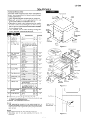
STEP REMOVAL
PROCEDURE
FIGURE
1 Top Cabinet
1. Screw...not to open the disc tray, take out
the CD tray cover, and close.
(Note 1)
2. When fining back the cam gear assembly, let it safe and ensure excellent performance: 1.
Service Manual - Page 7

... 7-3
2 Woofer
1. Screw D1) x4 7-3
Super Tweeter
(D1)x2 ø3x12mm Tweeter
Speaker Box (A2)x1
Super Tweeter
(C1)x2 ø3x12mm (D1)x2 ø3x12mm
CD-E99
Speaker Box
Passive Radiator
Figure 7-1 (B1)x1
(A1)x4 ø4x40mm
Woofer (B2)x4 ø4x16mm
Figure 7-3
(A3)x4 ø4x16mm
Screwdriver
Driver should be...
Service Manual - Page 8

... "Fusible" is a fuse type.
• Capacitor: To indicate the unit of capacitor, a symbol P is used : the symbol K means 1000 ohm and the symbol M means 1000 kohm and the resistor without such a symbol is ohm-type resistor. CD-E99
NOTES ON SCHEMATIC DIAGRAM
• Resistor: To differentiate the units of resistors, such symbol as...
Service Manual - Page 9

...) D_GND +6.5V (+B4) CNP5
TO MAIN SECTION 12 345 67 8
WRQ DRF CE DO DI CL CD RES CLAMP SW O/C, DISC NO CNP6
SW1 OPEN/CLOSE
TO DISPLAY SECTION 1 2 3 4 5 6 7 8 9 10
SW2 CLAMP
SW3
DISC
NUMBER
+
CD-E99
M
- 1 2 3 4 5 6 1 2 3 4 5 6 1 2 3 4 5 ...57
64 DO
56
65 *WRQ
55
66 *RES
51
67 DRF
50
43
IC1
44
LC78646E
40
CD SERVO
37
28 48 XOUT
19
6
49 XIN
CONT 5 26
SLDO 23 SPDO 22
FD0 21 ...
Service Manual - Page 10

...
SYSTEM
MICROCOMPUTER
(2/2)
SYSTEM MUTE
VF1
Figure 10 BLOCK DIAGRAM (2/3) - 10 - TAPE 2
P.B. CD-E99
AM LOOP ANTENNA
FM ANTENNA
IC301 TA7358AP FM FRONT END FM IF
+B6
+B5
ZD351
+B6
+B6
5.1V
10.7 ...R
BI601
1
CNP5 FROM CD SECTION
2
3
+B5
23
L9
DI 1
R 16
CE 2
TAPE TUNER
L 10 R 15 L 11 R 14
IC601 CLK LC75341 AUDIO PROCESSOR
24 21
-20dB ATT Q601
Q602 R
CD L 12
4L
R 13...
Service Manual - Page 11

... CORD AC 120 V, 60 Hz CD-E99
Q603 Q604
C/PLAY
T1/T2 BIAS E 47 W M PUTER
SYSTEM
MUTE
VF1
-VF VF2
1 5 ~ 19
FL701 FL DISPLAY
27 ~ 32 33 ~ 41 45
TO CD SECTION
+B10
TAPE MECHANISM
ASS'Y
...RESET VDD CE CLK DI DO
15
41
~
1 2 4 5 6 7 8 10 11 12 16 17 20 21 22 23 24
RX701
REMOTE 3 SENSOR 1
2
+B10
KEY SW701-SW707
SW711-SW718
SW721-SW724
+B10
SP DET.
L 18
11 L-OUT
R 14 7
6
251
8 ...
Service Manual - Page 12

... DIAGRAM can be found on page 8.
1
2
3
4
5
6
Figure 12 SCHEMATIC DIAGRAM (1/10) - 12 - CD-E99
CNS601
A
1 R-CH
BI601 1
P21 12 - D TO CD SERVO PWB
CNP5
A_GND
2
3
L-CH 3
4
CD_GND
4
5
CD_+B
+B
5
6
6
7
+B
D_GND
7
... GR R612 390
R601 1K
R602 1K
C652 220P C651 220P
IC601
LC75341
C653 220P
AUDIO PROCESSOR
C601 220/16
R605 10K
C609 1/50
R607 3.9K
C607 0.12
C611 0....
Service Manual - Page 13

...0V
C138 0.0082
R145
4.7
R135 10K
C139 0.039(ML)
L103 330 µH
C140 47/25
M_GND TAPE_A_GND AGND (AUDIO PRO) A+10V +B_PROTECT D_GND M_+13V SW_5V SP_DET SP_RLY
+B +B +B
19
20 21
22 23 24 25 26 27...4.7/50 1/50 1/50 1/50
R1 13 C624 1/50
R644 6.8K R643 6.8K
R642 10K R641 10K
+B +B
CD-E99
MAIN PWB-A1(1/3)
R691 6.8K R690 6.8K
C691 390P C690 390P
R693 33K R692 33K
L-CH
JK690 VIDEO/AUX
...
Service Manual - Page 14

...HB)
AM BAND COVERAGE fL
C334 22P (CH)
BF301
BAND PASS FILTER
IC301
AM LOOP
C
ANTENNA
FM
1 2 3
TA7358AP FM FRONT END
ANTENNA
CNP301
C303 10P
1 1 2 2 3 3
1 2 3 4 5 6
7 8 ...
3
4
5
6
Figure 14 SCHEMATIC DIAGRAM (3/10) - 14 - CE CD-E99
C302 0.001
A
AM TRACKING
C338 D301
0.001 DS1SS133
C323 0.022
T303 AM ANTENNA
C330 15P (UJ)
C331 0.047 C332 0.022
D302 DS1SS133
B
T306
AM OSC...
Service Manual - Page 16

CD-E99
R939
+
A
-
+
-
IC901 STK41243 POWER AMP.
H TO MAIN SECTION R859 22K C863 22/50
D 14 A_GND 15
16
R-CH
SP_DET 27
SP_RLY 28
25
M_+13V +B
E
10
LD+7V
+B
R961
22
A+10V
+B
1
+B_PROTECT 23
12
D+5V
+B
A_5V
+B
F
11
SW_5V
+B
26
CD_GND 13
AGND(AUDIO PRO) 21
19
M_GND
G
D_GND
24
CD_D_GND 17
CD_A_GND...
Service Manual - Page 17

... 47/50
R803 12K
C801 100/35
R801 100K
D846 DS1SS133
C844 0.047/250
CNP802
ZD801 DZ6.2BSA
C802 47/50
R806 47K
P19 12 - CD-E99
MAIN PWB-A1 (3/3)
C925 47/50
03 99 GR
R962 47K
R934 56K
R937 56K R935 56K
L902 3µH
R
L R
L901 3µH
L
C929 0.1 (ML)
-B
BI801 1
3 4 5 6 7 8 9 10...
Service Manual - Page 18

...R779 10K
H
• NOTES ON SCHEMATIC DIAGRAM can be found on page 8.
1
2
3
4
5
Figure 18 SCHEMATIC DIAGRAM (7/10) - 18 - CD-E99
A
LED A PWB-A4
BI703 1
+10V +B
1
1
LED703 A503BC2E
2
2
2
CNS703
R751 330
LED DRIVER Q710
KRC102 M
2
3
1
CNP703
...2
AC_RLY VDD TIMER LED T_MOTOR T_SOL_A T_SOL_B SMUTE VSS REMOCON SP DET CD CLAMP SW P_IN AVREF
R746 R734 R735
54 O/C_SW 1K
53 1K
...
Service Manual - Page 20

...
• NOTES ON SCHEMATIC DIAGRAM can be found on page 8.
1
2
3
4
5
6
Figure 20 SCHEMATIC DIAGRAM (9/10) - 20 - C37 0.1 C36 0 22/50
CD-E99
A PICKUP UNIT 1
CD SERVO PWB-C
CD SIGNAL
CNS1B CNS1A
HPC1LX
B
VCC
7
7
VCC
7
7
VREF 6
6
6
6 VREF
E
5
5
5
5 E R6 22K
A
4
4
4
4 A R5 8.2K
B
3
3
F
2
2
3
3 B R4 8.2K
2
F 2
R3
22K
C
1
1
1
1 C
R1 8.2K
CNP1
C
C1...
Service Manual - Page 21

... 54
8 FIN2 B 9 TIN1 E 10 TIN2 F 11 VREF 12 REF1
IC1 LC78646E CD SERVO
EFLG 53 C2F 52
XVSS 51 FSX/16MIN 50
XIN 49
XL1 16.9344 MHz
... R19
15K
R8 10K
+B
+B
FOCUS/TRACKING/SPIN/ SLED DRIVER
+B
R21
1
R46
1
+B
C15 0.001
+B +B
L1 0.82 µH
CD-E99
CNS701 P19 12 - D FROM DISPLAY PWB
DRF CD RES WRQ
1
2
CE
3
+B
DO
4
+B
DI
5
CL
6
7 CLAMP SW
8 O/C,
9 DISC NO
10
CNP6
C42 0.01 ...
Service Manual - Page 31

... Distributor to replace parts with " " are important for the electrolytic capacitors, error is ±20%.
MODEL NUMBER
2. REF. Be sure to order.
3. CD-E99
PARTS GUIDE
MINI COMPONENT SYSTEM
MODEL CD-E99
CD-E99 Mini Component System consisting of capacitors/resistors parts codes
Capacitors
VCC Ceramic type VCK Ceramic type VCT Semiconductor type VC • • MF Cylindrical...
Service Manual - Page 44

... Audio Systems Division Higashihiroshima, Hiroshima 739-0192, Japan
Printed in any form or by any means, electronic, mechanical, photocopying, recording, or otherwise, without prior written permission of the publisher. No part of this publication may be reproduced, stored in a retrieval system, or transmitted in Japan A0302-1459DS•HA•M SC
CD-E99...
Similar Questions

Cd 'can't Read' Message
My CD player reads "can't read" when I insert a cd and/or a cd cleaner. This happens with all 5 slot...
My CD player reads "can't read" when I insert a cd and/or a cd cleaner. This happens with all 5 slot...
(Posted by wieve1 5 months ago)

My Sharp Stereo Was Working Fine Until I Moved. Now I Can't Play The Radio.cant
read none of my cds!!
read none of my cds!!
(Posted by bumpaflorida1 10 months ago)


Er Cd11 Error Message
I cannot open/close CD's and cannot play CD's. All else works fine. Any help would be appreciated! T...
I cannot open/close CD's and cannot play CD's. All else works fine. Any help would be appreciated! T...
(Posted by susanpembroke 10 years ago)

Screen Only Says 'good-bye' And Cd Player Won't Work
I have a year old Sharp CD-DH950. Cd player just stopped working, screen says "good-bye". I unplugge...
I have a year old Sharp CD-DH950. Cd player just stopped working, screen says "good-bye". I unplugge...
(Posted by kpstds 11 years ago)