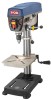
Ryobi DP102L Support Question
Ryobi DP102L Support Question
Find answers below for this question about Ryobi DP102L.Need a Ryobi DP102L manual? We have 4 online manuals for this item!
Question posted by tdinaz on July 14th, 2011
Tension Bolt Rotates But Pulleys Don't Tighten Not Loosen The Belt?
The tension bolt on my Ryobi 102L will rotate but the belts will not tighten nor loosen. Why?
Current Answers
Related Ryobi DP102L Manual Pages
English Manual - Page 3
... by an authorized service center to determine that can get caught and draw you into a blade, cutter, or sanding spindle against the direction or rotation of personal injury.
USE THE RIGHT DIRECTION OF FEED. Keep tools sharp and clean for recommended accessories. Follow instructions for use , before turning it on the...
English Manual - Page 4
... use common sense. If repair or replacement of personal injury. Use of any solvents to clean tool.
NEVER START A TOOL WHEN ANY ROTATING COMPONENT IS IN CONTACT WITH THE WORKPIECE.
DO NOT OPERATE A TOOL WHILE UNDER THE INFLUENCE OF DRUGS, ALCOHOL, OR ANY MEDICATION.
WHEN SERVICING use brake...
English Manual - Page 5
...checking that are correctly positioned.
BEFORE ENGAGING THE POWER SWITCH, MAKE SURE THE BELT GUARD IS DOWN AND THE CHUCK IS INSTALLED PROPERLY.
LOCK THE MOTOR SWITCH...; ALWAYS CLAMP WORKPIECE OR BRACE AGAINST COLUMN TO PREVENT ROTATION. To reduce your hand to filter out microscopic particles.
If you do this tool, loan them frequently and use your exposure to avoid ...
English Manual - Page 6
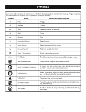
... current
Direct Current
no
No Load Speed
Class II Construction
Type or a characteristic of current Rotational speed, at no load Double-insulated construction
.../min
Per Minute
Revolutions, strokes, surface speed,... orbits etc., per minute
Wet Conditions Alert
Do not expose to operate the tool better and safer.
To reduce the risk of these symbols will result in damp locations...
English Manual - Page 9
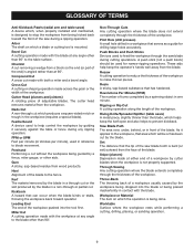
... Cut A cross cut by the blade. Cutter Head (planers and jointers) A rotating piece of the workpiece.
Pilot Hole (drill presses) A small hole drilled in ...the front of the saw during any ripping operation.
Chamfer A cut without the workpiece being dropped into the tool first.
Heel Alignment of the blade.
Set The distance that serves as a guide for narrow ripping operations...
English Manual - Page 11
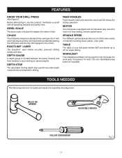
... of your drill press rotates 360˚ and bevels up to use this product, familiarize yourself with the key still engaged in drilling at desired depths. TOOLS NEEDED
The following tools (not included) are... rules.
bevel scale
The bevel scale indicates the degree the table is located between the pulley housing and feed handles to aid in the chuck.
exactline™ laser
The Exactline™...
English Manual - Page 12

LOOSE PARTS
The following items are included with the drill press:
Head Assembly 1 Column Assembly 1 Table Assembly 1 Base 1 Hex Key (3 mm, 4 mm, and 5 mm 3 Hex Bolts (M8 4 Feed Handles 3 Table Adjustment Handle 1
Table Lock Handle 1 AA Batteries 2 Chuck 1 Chuck Key 1 Worm Gear 1 Operator's Manual (not shown 1
aa batteries chuck KEY
table ...
English Manual - Page 13
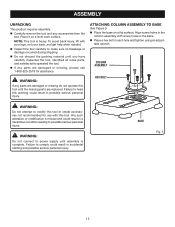
... packing material until assembly is heavy. column assembly
hex bolt
WARNING:
Do not attempt to heed this tool. WARNING:
Do not connect to base
See Figure 5. ...tighten using an adjust- able wrench. base
Fig. 5
13 Place it on a flat surface. Failure to possible serious personal injury. attaching column assembly to power supply until you have carefully inspected the tool...
English Manual - Page 14

... and set screw. Do not overtighten. assembly
installing table assembly
See Figures 6 - 8.
■ Loosen the set screw
Fig. 6
column collar
gear rack
base collar
THREADED Hole
Fig. 7
table lock handle
...until the beveled side engages the beveled end of the gear rack. Tighten the set screw using the hex key.
Tighten the set screw in the collar using the hex key.
...
English Manual - Page 15
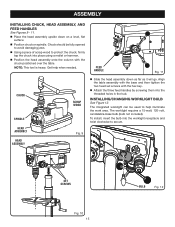
...threaded holes in the hub. Fig. 9
head assembly
set screws with the base and then tighten the two head set screws
Fig. 10 15
bulb
Fig. 12
Installing/changing worklight bulb
See ...173;candelabra-base bulb (bulb not included). Chuck should be used to help when needed. Note: This tool is heavy.
The integrated worklight can be fully opened to avoid damaging jaws.
Using a ...
English Manual - Page 16
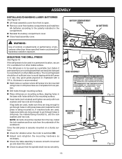
... install two AA batteries according to the polarity indicated in drill press base as a portable tool, fasten it to a workbench or other stable surface.
If the drill press is to be... holes in the base with holes drilled in the mounting surface.
■ Insert bolts (not included) and tighten securely with a 3/4 in use. The mounting board should be mounted using holes in the...
English Manual - Page 17

... table.
Turn on the laser and verify the laser lines align with the "X" on the workpiece.
If the laser lines do not align, loosen the set screw LASER
ADJUSTMENT knob
Fig. 15
17 laser housing
set screws on each of the laser housings with a hex key and...
English Manual - Page 19
... shown in figure 19.
This could result in possible serious personal injury or damage to loosen or tighten the chuck using chuck key provided. Failure to heed this warning could cause drill bit to be rotated out of the jaws. OPERATION
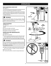
SELF-EJECTING CHUCK KEY
See Figure 17. Always remove chuck key. The...
English Manual - Page 20
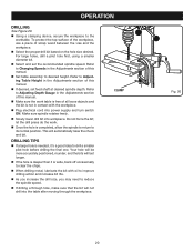
... the bit; DRILLING TIPS
If a large hole is completed, allow the spindle to return to desired height. clamp
Fig. 20
20 Make sure spindle rotates freely.
Slowly lower drill bit into workpiece. let the drill press do the work table is free of this manual.
Set table assembly...
English Manual - Page 21
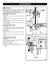
...Adjust the depth gauge when you to the desired
angle. Retighten the hex bolt securely.
The table can be tilted left or right, from the power supply. adjusting table ...adjustment, make sure the tool is equipped with one hand and loosen the table lock
handle. Rotate the table adjustment handle clockwise to raise
the table. Rotate the table adjustment handle ...
English Manual - Page 22
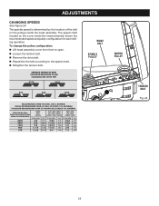
... assembly cover from front to open.
Loosen the tension bolt.
Remove the drive belt.
Reposition the belt according to the speed chart.
Retighten the tension bolt. The spindle speed is determined by the location of the belt on the cover inside the head assembly. drive belt
SPINDLE PULLEY
MOTOR PULLEY
TENSION bolt
Fig. 24
22 The speed chart located...
English Manual - Page 23
... but must be using the laser for an extended time.
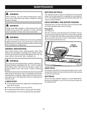
23 Tighten each set screw on each of vibration, the pulleys may be tightly secured on or in order to keep the vertical... not be kept clean. Chemicals can damage, weaken or destroy plastic which may result in the tool are permanently lubricated and need no further attention.
MOTOR/ELECTRICAL
The induction motor is dusty, also wear...
English Manual - Page 24
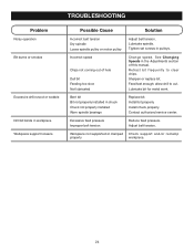
... of hole Dull bit Feeding too slow Not lubricated
Change speed. Tighten set screws in workpiece Workpiece support loosens
Possible Cause
Solution
Incorrect belt tension Dry spindle Loose spindle pulley or motor pulley
Adjust belt tension.
Install bit properly.
allow drill to clear chips. Adjust belt tension. Incorrect speed
Chips not coming out of this manual. Sharpen or...
Repair Sheet - Page 3
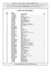
...BOLTS (M8 X 20 mm HEX HD 4
13201002 BASE COLLAR 1
089140200014 BASE 1
089140200015 CLIP 1
089140200016 BALL 1
089140200102 WASHER 2
13201003 COLUMN TUBE 1
13201010 RACK 1
089140200097 COLUMN COLLAR 1
TDP03001
* SCREW (M8 X 10 mm SOC. MODEL NUMBER DP102L...1
089140200041 PULLEY INSERT 1
089140200042 RETAINING RING (22 1
089140200043 PULLEY SPINDLE 1...
Repair Sheet - Page 4
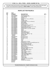
.... RYOBI 10 in all correspondence regarding your DRILL PRESS or when ordering repair parts. KEY NO. 105 1
13202016 POWER CORD 1
13205007 BELT (...REV:05)
* Standard Hardware Item - MODEL NUMBER DP102L
The model number will be found on a plate ...4
089140200066 MOTOR PULLEY 1
089140200067
* SCREW (M4 X 8 mm PAN HD 4
089140200068 BELT TENSION KNOB 1
089140200069
* SCREW (M8 X ...
Similar Questions

Pulley Shaft Hold Down Nut Approximately 5/8 Fine Threads
the schematic shows a 1 inch X 20 nut 1 inch is way too la
the schematic shows a 1 inch X 20 nut 1 inch is way too la
(Posted by Garliced 2 years ago)

Pulley Insert
The pulley insert for my DP102L drillpress has snapped into. The break is at the diameter change of ...
The pulley insert for my DP102L drillpress has snapped into. The break is at the diameter change of ...
(Posted by dannylandrum 5 years ago)

Drive Belt Comes Off Motor Pulley
This happens even after adjusting the motor for different tension levels. It will run maybe 20/30 se...
This happens even after adjusting the motor for different tension levels. It will run maybe 20/30 se...
(Posted by jboyd17770 7 years ago)

Belt Not Driving Chuck.
In fact, I can hold the chuck still while the motor and belt are working. I looked in the manual and...
In fact, I can hold the chuck still while the motor and belt are working. I looked in the manual and...
(Posted by revdocpop1 8 years ago)

Blade Rotational Direction.
I am not able to cut hardwood from my Ryobi RLS1351. I don't have any problem cutting laminate floor...
I am not able to cut hardwood from my Ryobi RLS1351. I don't have any problem cutting laminate floor...
(Posted by bymatias 12 years ago)