Gigabyte GA-P55M-UD2 Support Question
Gigabyte GA-P55M-UD2 Support Question
Find answers below for this question about Gigabyte GA-P55M-UD2.Need a Gigabyte GA-P55M-UD2 manual? We have 2 online manuals for this item!
Question posted by wrkarenz on February 18th, 2014
Wiring Diagram For Ga-p55m-ud2
I pulled the wires out the HD LED, power sw., etc and I need a wiring diagram in order to get them back in the right positions. Please send me diagram for these 8 wires
Current Answers
Answer #1: Posted by bernadette2013 on February 18th, 2014 1:16 PM
bernadette2013

Member since:
September 7th, 2013 Points: 485,260

Member since:
September 7th, 2013 Points: 485,260
Related Gigabyte GA-P55M-UD2 Manual Pages
Manual - Page 1

... avoid risk of
hardware damage or lost of a button, X.H.D helps to enhance your needs and hardware components.
3.
To automatically set up a RAID 0 array
later using the ... utility only supports the SATA controllers integrated in the array. )
1. To manually set up all motherboard drivers, including the X.H.D utility. All with which you 'll not be recognized during the Windows ...
Manual - Page 1
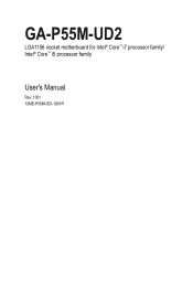
GA-P55M-UD2
LGA1156 socket motherboard for Intel® Core™ i7 processor family/ Intel® Core™ i5 processor family
User's Manual
Rev. 1001 12ME-P55MUD2-1001R
Manual - Page 3

... TECHNOLOGY CO., LTD. For product-related information, check on our website at: http://www.gigabyte.com.tw
Identifying Your Motherboard Revision The revision number on our website. All rights reserved.
Documentation Classifications
In order to their respective owners. For instructions on how to the specifications and features in this manual may be made...
Manual - Page 4

Table of Contents
Box Contents...6 Optional Items...6 GA-P55M-UD2 Motherboard Layout 7 Block Diagram...8
Chapter 1 Hardware Installation 9 1-1 Installation Precautions ... Tweaker(M.I.T 37 2-4 Standard CMOS Features 47 2-5 Advanced BIOS Features 49 2-6 Integrated Peripherals 51 2-7 Power Management Setup 54 2-8 PC Health Status 56 2-9 Load Fail-Safe Defaults 58 2-10 Load Optimized ...
Manual - Page 6
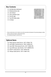
... (Part No. 12CR1-1UB030-5*R) 2-port IEEE 1394a bracket (Part No. 12CF1-1IE008-0*R) 2-port SATA power cable (Part No. 12CF1-2SERPW-0*R) S/PDIF In cable (Part No. 12CR1-1SPDIN-0*R) COM port cable (Part No. 12CF1-1CM001-3*R)
- 6 - Box Contents
GA-P55M-UD2 motherboard Motherboard driver disk User's Manual Quick Installation Guide One IDE cable Two SATA 3Gb/s cables I/O Shield...
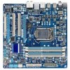
Manual - Page 7

GA-P55M-UD2 Motherboard Layout
KB_USB R_SPDIF R_USB_2
CPU_FAN ATX_12V_2X4
LGA1156
PHASE LED ATX
IT8720
GA-P55M-UD2
DDR3_2 DDR3_1 DDR3_4 DDR3_3
R_USB_1 USB_1394_ESATA
USB_LAN
RTL8111D
AUDIO
BAT
F_AUDIO PCIEX16
PCI1 CODEC
PCI2 CD_IN
PCIEX4
SPDIF_O
SPDIF_I
FDD
B_BIOS M_BIOS
IDE
GIGABYTE SATA2
...
Manual - Page 8
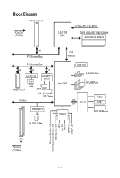
Block Diagram
1 PCI Express x16
PCIe CLK (100 MHz)
LGA1156 CPU
CPU CLK+/- (133 MHz)
DDR3 2200/1333/1066/800 MHz Dual Channel Memory
x16 PCI Express ...
Manual - Page 9
...; Do not place the computer system on an uneven surface. • Do not place the computer system in a high-temperature environment. • Turning on the motherboard, make sure the power supply voltage has been set according to the local voltage standard. • Before using the product, please verify that all cables and...
Manual - Page 12
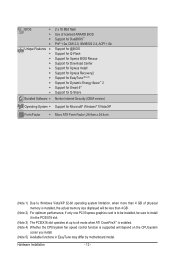
... CPU/system fan speed control function is supported will depend on the CPU/system
cooler you install. (Note 5) Available functions in EasyTune may differ by motherboard model.
Manual - Page 15
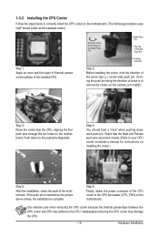
... below to the CPU. Push down each push pin. Step 4:
You should hear a "click" when pushing down on the motherboard.
Check that the Male and Female push pins are joined closely. (Refer to the CPU fan header (CPU_FAN) on the push....)
Step 1: Apply an even and thin layer of the installed CPU. Step 6:
Finally, attach the power connector of the motherboard. Hardware Installation
Manual - Page 16

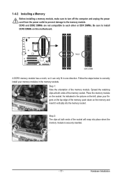
... memory support list.) • Always turn off the computer and unplug the power cord from the power outlet before installing the memory to prevent hardware damage. • Memory modules ...(Go to insert the memory, switch the direction.
1-4-1 Dual Channel Memory Configuration
This motherboard provides four DDR3 memory sockets and supports Dual Channel Technology. When enabling Dual Channel mode ...
Manual - Page 17
... Memory
Before installing a memory module, make sure to turn off the computer and unplug the power cord from the power outlet to prevent damage to install DDR3 DIMMs on the socket. Notch
DDR3 DIMM
A DDR3 ... direction. Step 1: Note the orientation of the memory socket.
Place the memory module on this motherboard. DDR3 and DDR2 DIMMs are not compatible to each other or DDR DIMMs. Be sure to ...
Manual - Page 18

...card. • Always turn off the computer and unplug the power cord from the power outlet before you begin to release the card and then pull the card straight up from the slot. 1-5 Installing an Expansion... slot to install an expansion card: • Make sure the motherboard supports the expansion card. Make sure the card is fully inserted into the slot. 4. Hardware Installation
- 18 -
Manual - Page 23
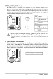
...the CPU or the system may result in the correct orientation (the black connector wire is typically designated by a stripe of the connector and the floppy disk drive...
CPU_FAN: Pin No. Most fan headers possess a foolproof insertion design. 3/4) CPU_FAN/SYS_FAN (Fan Headers)
The motherboard has a 4-pin CPU fan header (CPU_FAN) and a 4-pin (SYS_FAN). For purchasing the optional floppy disk...
Manual - Page 26
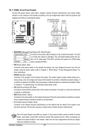
..., speaker, chassis intrusion switch/sensor and system status
indicator on the chassis front panel. Note the positive and
negative pins before connecting the cables. Message/Power/ Power Sleep LED Switch
Speaker
MSG+ MSG- PW+ PWSPEAK+ SPEAK-
2
20
1
19
HD+ HD-
One single short beep will be heard if no problem is on the chassis that can...
Manual - Page 27

... even damage it. For HD Front Panel Audio: For AC'97 Front Panel Audio:
Pin No. Hardware Installation Make sure the wire assignments of the module connector match the pin assignments of the front and back panel audio connections simultaneously. Incorrect connection between the module connector and the motherboard header will be present...
Manual - Page 34

...POST screen. The system will display a message during the POST. Motherboard Model BIOS Version
P55M-UD2 D8 . . . .
: BIOS Setup : XpressRecovery2 : Boot ...message again. After system restart, the device boot order will appear again at next boot if you ... Menu allows you want to change the first boot device setting as needed.
: Q-FLASH Press the key to access the Q-Flash utility directly...
Manual - Page 52

.../PD: Value
F10: Save
F6: Fail-Safe Defaults
ESC: Exit
F1: General Help
F7: Optimized Defaults
This motherboard incorporates cable diagnostic feature designed to the motherboard, the Status fields of all four pairs of wires will dynamically detect if a LAN cable is detected on the LAN cable connected to the following message will...
Manual - Page 53

... and GSATA2_0/1 Connectors) Enables or disables the IDE and SATA controllers integrated in IDE mode.
Advanced Host Controller Interface (AHCI) is the approximate length of wires, the Status field will show Short and then length shown will show Open, and the length shown is an interface specification that allows the storage...
Manual - Page 68

...
1. Note: You can update the system BIOS without the need to access Q-Flash.
P55M-UD2 D8 . . . .
: BIOS Setup : XpressRecovery2 : Boot Menu : Qflash 07/16/2009-P55-7A89RG0EC-00
Because BIOS flashing is saved to -use FAT32/16/12 file system.
3. 4-2 BIOS Update Utilities
GIGABYTE motherboards provide two unique BIOS update tools, Q-Flash™ and...
Similar Questions

Mother Board No Display Show
2 green led one orange and one red led power show but after a few second motherboard fan is off
2 green led one orange and one red led power show but after a few second motherboard fan is off
(Posted by abdulraufbhutta429 3 years ago)


Gigabyte Ga-k8nf-9-si Motherboard Connection
Where are the Power SW and HDD LED connections connected to the Gigabyte GA-K8NF-9-SI Motherboard?
Where are the Power SW and HDD LED connections connected to the Gigabyte GA-K8NF-9-SI Motherboard?
(Posted by jamie2u123456 11 years ago)
Pls. Send Me A Pdf Wiring Installation Guide For My Motherboard Ga-h61m-ds2..thn
(Posted by DAVIDJR1261 11 years ago)
Contact The Wires Case
hi please tell how can i Contact the wires of case ( for example hdd power -led power .....) to the...
hi please tell how can i Contact the wires of case ( for example hdd power -led power .....) to the...
(Posted by haebrahimi999 12 years ago)