Dell Vostro 470 Support Question
Dell Vostro 470 Support Question
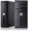
Find answers below for this question about Dell Vostro 470.Need a Dell Vostro 470 manual? We have 2 online manuals for this item!
Question posted by donmcmanman on January 13th, 2013
Monitor Cable
Hello,
I'm setting up the Vostro 470.
I get this message: "Plug the monitor cable into the add-in graphics card connector. This may require a video adapter or video adapter cable (provided with the system)."
Where is the correct connection?
I have a peice called VGA 7P365 A00. Is that the video "graphics adapter cable?"
Don
Current Answers
Answer #1: Posted by NiranjanvijaykumarAtDell on January 14th, 2013 4:51 AM
NiranjanvijaykumarAtDell

Member since:
May 12th, 2012 Points: 807,180

Member since:
May 12th, 2012 Points: 807,180
Hello donmcmanman,
I am from Dell Social Media and Community.
Yes, the VGA cable is the cable used to connect from the monitor to the computer. Please view the attached image for clarification.
If this has not helped you or if you need any further assistance, feel free to message me on Twitter. I will be happy to assist.
Dell-Niranjan
Twitter: @NiranjanatDell
Supporting Image
You can click the image below to enlarge
NiranjanAtDell
Dell Inc
Related Dell Vostro 470 Manual Pages
User Manual - Page 1
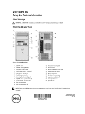
...connectors (2)
12. power connector 17. back panel connectors 18. security cable slot 20. media card readers (optional) 5. CD/DVD drive eject buttons (2) 9. power supply diagnostic light 15. voltage selector switch 16. microphone connector...the computer. expansion card slots (4) 19. powered USB 2.0 connector 10. USB 2.0 connector 11. Dell Vostro 470
Setup And Features ...
User Manual - Page 2
...: Before you did not order them.
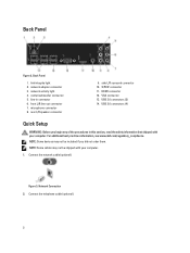
network adapter connector 3. rear L/R speaker connector
9. Connect the network cable (optional). Back Panel
Figure 2. VGA connector 13. Connect the telephone cable (optional).
2 Back Panel
1. NOTE: Some devices may not be included if you begin any of the procedures in connector 6. NOTE: Some cables may not be shipped with your computer...
User Manual - Page 3
....
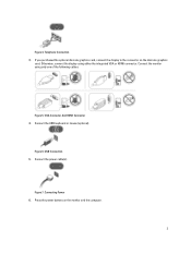
3 Otherwise, connect the display using only one of the following cables:
Figure 5. Connect the monitor using either the integrated VGA or HDMI connector. Figure 6. VGA Connector And HDMI Connector 4.
Press the power buttons on the discrete graphics
card. Telephone Connection 3. Connect the power cable(s). USB Connection 5. Figure 7.
Connect the USB keyboard or mouse...
User Manual - Page 5

... proprietary interest in this text: Dell™, the DELL logo, Dell Precision™, Precision ON™,ExpressCharge™, Latitude™, Latitude ON™, OptiPlex™, Vostro™, and Wi-Fi Catcher™ are either the entities claiming the marks and names or their products, Dell Inc. Information in trademarks and trade...
Owner's Manual - Page 2
.... Trademarks used in this text: Dell™, the DELL logo, Dell Precision™, Precision ON™,ExpressCharge™, Latitude™, Latitude ON™, OptiPlex™, Vostro™, and Wi-Fi Catcher™ are registered trademarks or trademarks of Intel Corporation in trademarks and trade names other countries. AMD® is a registered...
Owner's Manual - Page 5
... metal surface, such as a processor by its edges, not by its metal mounting bracket. Hold a component such as a connector on a card.
Some cables have read the safety information that both connectors are disconnecting this type of cable, press in this document assumes that came with your computer and certain components may only be replaced or...
Owner's Manual - Page 6
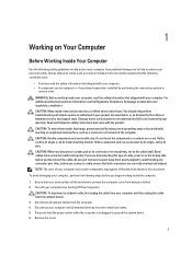
... Click Start , then click the arrow in this document may require the following tools: • Small flat-blade screwdriver •...6 CAUTION: To connect a network cable, first plug the cable into the network device and then plug it into the computer.
2. Shut... → Turn Off . Connect any external devices, cards, and cables before you work, periodically touch an unpainted metal surface ...
Owner's Manual - Page 13
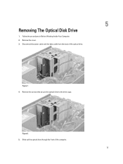
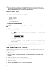
Figure 7. 4. Remove the screws that secure the optical drive to the drive cage. Disconnect the power cable and the data cable from the back of the computer.
13
Slide out the optical drive through the front of the optical drive. Follow the procedures in Before Working Inside Your Computer. 2. Remove the cover. 3. Figure 8. 5.
5
Removing The Optical Disk Drive
1.
Owner's Manual - Page 14
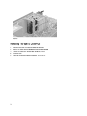
Replace the screws that secure the optical drive to the optical drive. 4. Connect the power cable and data cable to the drive cage. 3. Install the cover. 5. Installing The Optical Disk Drive
1.
Slide the optical drive in After Working Inside Your Computer.
14 Follow the procedures in through the front of the computer. 2. Figure 9.
Owner's Manual - Page 15
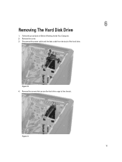
Figure 10. 4. Disconnect the power cable and the data cable from the back of the hard drive. Remove the screws that secure the hard drive cage to the chassis. Remove the cover. 3. Figure 11. 15 6
Removing The Hard Disk Drive
1. Follow the procedures in Before Working Inside Your Computer. 2.
Owner's Manual - Page 17

3. Install the cover. 5. Connect the power cable and data cable to the hard drive. 4. Follow the procedures in After Working Inside Your Computer.
17
Owner's Manual - Page 19

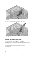
Remove the cover. 3. Disconnect the memory card cable from the retention clip. Figure 16. 5. Remove the screws that secure the memory card reader to the drive cage.
19 Figure 15. 4. 7
Removing The Memory Card Reader
1.
Unroute the memory card reader cable from the system board. Follow the procedures in Before Working Inside Your Computer. 2.
Owner's Manual - Page 20
...
1. Route the memory card reader cable through the front of the computer. 2. Install the cover. 6. Slide the multimedia card reader out through the retention clip. 4.
Slide the memory card-reader in After Working Inside Your Computer. 20 Replace and tighten the screws that secure the multimedia card-reader to the system board connector. 5. Follow the procedures...
Owner's Manual - Page 21
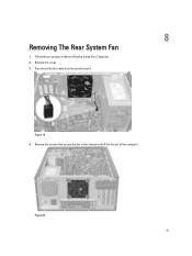
Remove the cover. 3. Remove the screws that secure the fan to the chassis and lift the fan out of the computer. Figure 20. 21 Disconnect the fan cable from the system board. Figure 19. 4.
8
Removing The Rear System Fan
1.
Follow the procedures in Before Working Inside Your Computer. 2.
Owner's Manual - Page 22
Reconnect the fan cable to the chassis. 3. Follow the procedures in place, replace the screws that secure the fan to the system board. 4. Install the cover. 5. While holding the chassis fan in After Working Inside Your Computer.
22 Installing The Rear System Fan
1. Place the fan towards the center of the computer into the chassis. 2.
Owner's Manual - Page 25
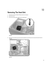
Remove the screws that secure the heat sink assembly to the system board and remove the heat sink from the system board.
10
Figure 22. 4. Remove the cover. 3. Disconnect the heat sink fan cable from the
computer. Figure 23. 25 Removing The Heat Sink
1. Follow the procedures in Before Working Inside Your Computer. 2.
Owner's Manual - Page 26

Follow the procedures in After Working Inside Your Computer.
26 Connect the heat sink fan cable to the system board. 3. Install the cover. 4. Install the screws that secure the heat sink assembly to the system board. 2. Installing The Heat Sink
1.
Owner's Manual - Page 55
...boot device available
No bootable partition on the system board might be wrongly set.
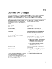
Diagnostic Error Messages
Description
Alert! System fan failure
Possible fan failure
CPU fan failure
CPU ....
If reseating the cable does not solve the problem, replace the keyboard. Hard Drive SELF MONITORING SYSTEM has reported that was running when the message appeared.
Hard-disk drive...
Owner's Manual - Page 57
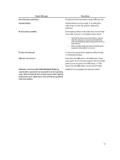
... be malfunctioning or motherboard failure. Hard Drive SELF MONITORING SYSTEM has reported that you back up your boot device, ensure that the cables are connected and that the drive is installed properly... and partitioned as a boot device.
• Enter system setup and ensure that the boot sequence information is correct. System Message...
Owner's Manual - Page 59
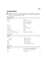
The following specifications are only those required by region. Dimensions Dimensions Height
without base with your computer. Memory Memory Connectors Type Speed
360.00 mm (14.17 ..., quad‑channel DDR3 up to 1600 MHz
59 Table 10. System Information
System Information
Model
Vostro 470
Processor
Intel Core i3 (2nd Generation)
Intel Core i5 (3rd Generation)
Intel Core i7 (3rd...
Similar Questions


How To Plug The Monitor Cable Into The Add-in Graphics Card Connector On A Dell
optiplex 745
optiplex 745
(Posted by hugiimac 10 years ago)

Enabling A Third Monitor Using Onboard Graphics Card On A Dell Vostro 220
How do you enable a third monitor using onboard graphics card on a Dell Vostro 220?
How do you enable a third monitor using onboard graphics card on a Dell Vostro 220?
(Posted by v00doo1 11 years ago)

Re Vostro 470 Desktop Front Panel Layout
There 4 USB ports - from left to right. No.1 has an 'lightning symbol appended to the USB sysmbol. N...
There 4 USB ports - from left to right. No.1 has an 'lightning symbol appended to the USB sysmbol. N...
(Posted by richard24277 11 years ago)