
Dell PowerEdge 2950 Support Question
Dell PowerEdge 2950 Support Question
Find answers below for this question about Dell PowerEdge 2950.Need a Dell PowerEdge 2950 manual? We have 8 online manuals for this item!
Question posted by xxttJungs on September 16th, 2013
How To Install Hot Swap Power Supply Poweredge 2950
The person who posted this question about this Dell product did not include a detailed explanation. Please use the "Request More Information" button to the right if more details would help you to answer this question.
Current Answers
Related Dell PowerEdge 2950 Manual Pages
Installing a SATA Optical Drive - Page 6

... chipset shroud.
NOTE: You may need to replace the existing power cable with the branching power cable) to the power supply connector. a Route the cable through the power cable cutout in a PowerEdge 1950 Drive Tray 2 3
1 4
5
1 optical drive 3 SATA power cable 5 optical drive carrier
2 SATA cable 4 carrier latch
Installing the SATA Optical Drive - b Bend the cable toward the chipset...
Installing a SATA Optical Drive - Page 7

... the system to the power supply connector. See "Closing the System" in the PowerEdge 1950 2
1
3
4
6
5
1 SATA data cable 3 chipset shroud 5 SATA power cable
2 SATA_A connector on the system and attached peripherals.
SATA Cable Routing in your Hardware Owner's Manual.
6 Close the system. Installing the SATA Optical Drive - PowerEdge 2970 or 2950
1 Insert the optical drive...
Installing a SATA Optical Drive - Page 9

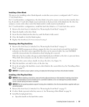
... and turn on the system board. For a PowerEdge 1900, use the SATA_B connector.
- For a PowerEdge 2900 system, connect to an available power supply cable.
5 Replace the center fan bracket. For a PowerEdge 2900, use the SATA_D connector. See Figure 1-5.
-
Installing the SATA Optical Drive - See Figure 1-5.
- See "Installing the Cooling Shroud" in your Hardware Owner's Manual.
10...
Information Update - Page 3
... III Systems 9 Processor Upgrades - Contents
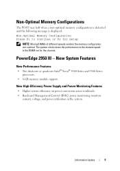
Non-Optimal Memory Configurations 5 PowerEdge 2950 III - New System Features 5
New Performance Features 5 New High-Efficiency Power Supply and Power Monitoring Features 5 New I/O and Storage Features 6 New Security Features 6 Optional Internal USB Memory Key 6 Installing the Optional Internal USB Memory Key 7 Support for 8-GB Memory Modules -
Information Update - Page 5
... power utilization in the DIMM set for Setup
NOTE: Mixing DIMMs of different speeds renders the memory configuration non-optimal. New System Features
New Performance Features
• Two dual-core or quad-core Intel® Xeon® 5400 Series and 5300 Series processors.
• 8-GB memory module support.
Information Update
5 PowerEdge 2950 III...
Getting Started Guide - Page 5

...RW/DVD drive. System Features
The major hardware and software features of your system by installing a second processor, you must order the processor upgrade kits from Dell contains the correct...of 533 or 667 (when available) MHz, Fully Buffered DIMMs (FBD), upgradable to two hot-pluggable, 750-W power supplies in the eight memory module sockets on systems with the 3.5-inch x4 and 2.5-inch x8...
Hardware Owner's Manual (PDF) - Page 4
... Installing a Hot-Plug Hard Drive 57
Replacing a Hard-Drive Carrier 58 Removing a Hard Drive From a Hard-Drive Carrier 58 Installing a SAS Hard Drive Into a SATAu Drive Carrier 59 Installing a SATA Hard Drive Into a SATA Drive Carrier 60 Installing a SATA Hard Drive and Interposer Card Into a SATAu Hard-Drive Carrier 61
Power Supplies 62 Removing a Power Supply 63 Replacing a Power Supply...
Hardware Owner's Manual (PDF) - Page 52
... 13
9
10 11 12
7 8
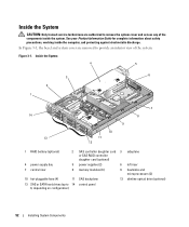
1 RAID battery (optional)
2 SAS controller daughter card 3 sideplane or SAS RAID controller daughter card (optional)
4 power supply bay
5 power supplies (2)
6 left riser
7 central riser
8 memory modules (8)
9 heatsinks and microprocessors (2)
10 hot-pluggable fans (4)
11 SAS backplane
12 slimline optical drive (optional)
13 SAS or SATA hard drives (up to 14 control...
Hardware Owner's Manual (PDF) - Page 54
... in reverse. Figure 3-2. Opening and Closing the System
CAUTION: Only trained service technicians are installing a hot-plug component such as a cooling fan or power supply, turn off the system and attached peripherals, and disconnect the system from the system.
54
Installing System Components See your Product Information Guide for complete information about safety precautions, working...
Hardware Owner's Manual (PDF) - Page 57
... drive bay. When both drive indicators are fully installed.
See the documentation supplied with 3.5-inch or 2.5-inch hard drives.
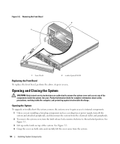
Removing a Hot-Plug Hard Drive
1 Remove the front bezel, if attached. Installing a Hot-Plug Hard Drive
NOTICE: When installing a hard drive, ensure that the drive can damage the partially installed carrier's shield spring and make it is fully...
Hardware Owner's Manual (PDF) - Page 62

See "Installing the Power Supply Blank" on the unoccupied power supply bay in the left power supply bay (1). If two power supplies are installed, the second power supply serves as a redundant, hot-plug power source. NOTICE: To ensure proper system cooling, the power supply blank must be installed on page 65.
62
Installing System Components If only one or two power supplies rated at ...
Hardware Owner's Manual (PDF) - Page 63
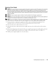
... VAC, and if two power supplies are connected to a power source in the redundant mode when two power supplies are installed and both power supplies are installed, the second power supply serves as a redundant, hot-plug power source. NOTICE: If only one power supply is installed, it interferes with only one power supply installed and without a power supply blank installed for the system to...
Hardware Owner's Manual (PDF) - Page 64

Remove the power supply blank only if you are installing a second power supply.
64
Installing System Components Removing and Installing a Power Supply
1 2 3
1 locking tab
2 cable retention bracket
3 power-supply handle
Replacing a Power Supply
1 With the power-supply handle in a non-redundant configuration. See Figure 1-4. Figure 3-8.
See Figure 3-8.
2 Rotate the handle down ...
Hardware Owner's Manual (PDF) - Page 65
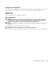
... secure with the Phillips screw. Installing the Power Supply Blank
To install the power supply blank, insert the tab on the right edge of the components inside the computer, and protecting against electrostatic discharge. System Fans
The system includes four hot-pluggable cooling fans. Removing a System Fan
CAUTION: Only trained service technicians are hot-pluggable. To maintain proper...
Hardware Owner's Manual (PDF) - Page 117
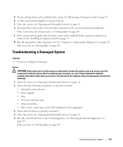
...Getting Help" on page 54. 2 Ensure that the following components are properly installed:
• Expansion cards and risers • Power supplies • Fans • Processors and heat sinks • Memory modules &#...the system.
See "Opening and Closing the System" on page 131. See "Using Server Administrator Diagnostics" on page 54. 6 Reconnect the system to remove the system cover and...
Hardware Owner's Manual (PDF) - Page 119
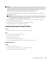
...panel LCD indicates a problem with only one power supply at a time in the redundant mode when two power supplies are installed. Remove and install only one power supply installed, without a power supply blank installed, can hot-plug the power supplies. NOTE: After installing a power supply, allow several seconds for the system to recognize the power supply and to determine if it .
See...
Hardware Owner's Manual (PDF) - Page 175
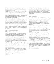
... systems to be integrated into an expansion slot. Windows Server 2003 - XML -
A battery-powered unit that allow data to display at a specific graphics resolution, you start -up and down. VGA - The logical circuitry that provides (in XML that automatically supplies power to your monitor must install the appropriate video drivers and your system's RAM.
A program...
Hardware Owner's Manual (PDF) - Page 178

...boot device, 76 indicator codes, 15
hot-plug hard drives, 57
I
indicators back-panel, 17 front-panel, 13 hard-drive, 15 NIC, 19 power, 18
installing control panel assembly, 106 diskette drive, ...riser board, 98 memory, 90 memory guidelines, 89 optical drive, 82 power supply blank, 65 processor, 93, 95 RAID battery, 74
installing (continued) SAS backplane board, 104 SAS controller daughter card, 70 ...
Cabling Instructions for the -48 VDC Power Supply - Page 1
Dell™ PowerEdge™ 2950 Systems
Cabling Instructions for the -48 VDC Power Supply
Dell™ PowerEdge™ 2950 系统
有关 -48 VDC
www.dell.com | support.dell.com
Cabling Instructions for the -48 VDC Power Supply - Page 3
Dell™ PowerEdge™ 2950 Systems
Cabling Instructions for the -48 VDC Power Supply
www.dell.com | support.dell.com
Similar Questions

How Do You Install Mounting Rails For Dell Poweredge 2950
(Posted by atanit 9 years ago)

How To Install Dell Redundant Power Supply Poweredge 2900
(Posted by mikkaneva 9 years ago)


How To Install Sas Controller Card In Poweredge 2950
(Posted by smadw1 10 years ago)
