Dell OptiPlex 990 Support Question
Dell OptiPlex 990 Support Question
Find answers below for this question about Dell OptiPlex 990.Need a Dell OptiPlex 990 manual? We have 3 online manuals for this item!
Question posted by rnkitkat on December 23rd, 2013
How To Remove Power Button On Dell 990 Tower
The person who posted this question about this Dell product did not include a detailed explanation. Please use the "Request More Information" button to the right if more details would help you to answer this question.
Current Answers
Related Dell OptiPlex 990 Manual Pages
User Manual - Page 1
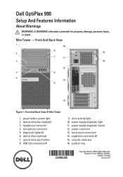
...And Back View
Figure 1. Front And Back View Of Mini Tower
1.
power supply diagnostic light 11. expansion-card slots (4) 15. power supply diagnostic button 12. padlock ring
Regulatory Model: D09M, D05D, D03S, D01U Regulatory Type: D09M001, D05D001, D03S001, D01U002 January 2011 Dell OptiPlex 990
Setup And Features Information
About Warnings
WARNING: A WARNING indicates a potential...
User Manual - Page 2
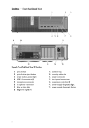
...11. optical-drive eject button 3. power connector 12. Front And Back View Of Desktop
1. USB 2.0 connectors (4) 5. expansion-card slots (4) 14. power button, power light 4. microphone connector 6. drive activity light 8. optical drive 2. padlock ring 10. Front And Back View
Figure 2. power supply diagnostic light 15. power supply diagnostic button
2 back panel connectors...
User Manual - Page 3
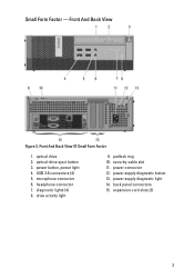
... Of Small Form Factor
1. drive activity light
9. back panel connectors 15. power button, power light 4. microphone connector 6. padlock ring 10. power supply diagnostic button 13. diagnostic lights (4) 8. Front And Back View
Figure 3. optical-drive eject button 3. security-cable slot 11. power connector 12. expansion-card slots (2)
3 Small Form Factor - optical drive...
User Manual - Page 4
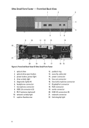
... connector 7. line-in/microphone connector 17. DisplayPort connector 18. diagnostic lights (4) 6. Front And Back View
Figure 4. network activity light 11. power connector 15. Ultra Small Form Factor - optical drive 2. Wi-Fi antenna (optional) 10. security-cable slot 14. USB 2.0 connectors (5) 21. power button, power light 4. network connector 22. optical-drive eject...
User Manual - Page 8

For a complete and current listing of the specifications for your computer. Figure 16. Press the power buttons on the monitor and the computer. Turning On Power
Specifications
NOTE: The following specifications are only those required by law to support.dell.com. System Information Chipset
Intel 6 Series Express chipset
Processor Processor
• Intel Core i3 series...
User Manual - Page 10
... test.
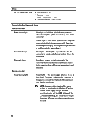
10 The power cable must be defective. two • Desktop - blinking blue light indicates sleep state of computer
Power supply light
Green light - When the system power supply voltage is turned on the diagnostic lights, see the Service Manual at the back of the power system by pressing the test button. Amber light -
Back...
System Board Mode Configuration - Page 1

... make sure that the computer is configured for property damage, personal injury, or death. Dell OptiPlex And Dell Precision System Board Mode Configuration
Introduction
This tech sheet covers the configuration process required after installing a new system board in your Dell desktop computer. chassis cover inside of the cover. FOR PROOF ONLY AMT ME Lockout
. . . 6 J0TTM...
Technical Guide - Page 2
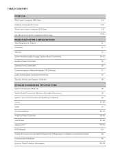
TABLE OF CONTENTS
OVERVIEW Mini Tower Computer (MT) View Desktop Computer (DT) View Small Form Factor Computer (SFF) View
Ultra Small Form Factor Computer (USFF) View MARKETING SYSTEM CONFIGURATIONS Operating System, Chipset Processor Memory Drives and Removable Storage, System Board Connectors Graphics/Video Controller External Ports/Connectors Communications-Network Adapter (NIC), Wireless Audio...
Technical Guide - Page 3
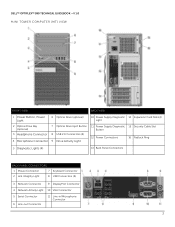
DELL™ OPTIPLEX™ 990 TECHNICAL GUIDEBOOK -V 1.0 MINI TOWER COMPUTER (MT) VIEW
FRONT VIEW
BACK VIEW
1 Power Button, Power Light
6 Optical Drive (optional)
10 Power Supply Diagnostic 14 Expansion Card Slots(4) Light
2 Optical Drive Bay (optional)
3 Headphone Connector
4 Microphone Connector
7 Optical Drive Eject Button 8 USB 2.0 Connectors (4) 9 Drive Activity Light
11 Power ...
Technical Guide - Page 4
DELL™ OPTIPLEX™ 990 TECHNICAL GUIDEBOOK -V 1.0
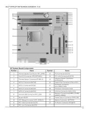
MT System Board Components
Number
Name
Number
...1 Connector(SATA1)
14
PCI-e 4x Connector(SLOT4)
15
Intrusion Switch Connector (INTRUDER)
16
System Fan Connector (FAN_HDD)
17
P2 Power Connector (12V_PWRCONN)
6
SATA 2 Connector(SATA2)
18
Processor Connector (N/A)
7
SATA 3 Connector(SATA3)
8
Internal USB Connector (INT_USB)...
Technical Guide - Page 5
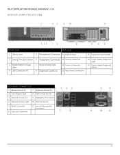
DELL™ OPTIPLEX™ 990 TECHNICAL GUIDEBOOK -V 1.0 DESKTOP COMPUTER (DT) VIEW
FRONT VIEW 1 Optical Drive
BACK VIEW 5 Microphone Connector 9 Padlock Ring
13 Expansion Card Slots(4)
2 Optical Drive Eject Button 6 Headphone Connector 10 Security Cable Slot
3 Power Button, Power Light
4 USB Connectors (4)
7 Drive Activity Light 8 Diagnostic Lights (4)
11 Power Connectors 12 Back Panel ...
Technical Guide - Page 6
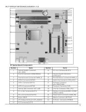
DELL™ OPTIPLEX™ 990 TECHNICAL GUIDEBOOK -V 1.0
DT System Board Components
Number
Name
1
Internal Speaker Connector
(INT_SPKR)
2
Front IO Connector (...
15
Thermal Sensor Connector(THRM_1)
16
System Fan Connector (FAN_HDD)
17
P2 Power Connector
(12V_PWRCONN)
18
Processor Connector (N/A)
19
CPU Fan Connector (FAN_CPU)
20
Memory Connectors(DIMM1, DIMM2,
DIMM3, DIMM4)...
Technical Guide - Page 7
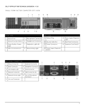
DELL™ OPTIPLEX™ 990 TECHNICAL GUIDEBOOK -V 1.0 SMALL FORM FACTOR COMPUTER (SFF) VIEW
FRONT VIEW
1 Optical Drive
5 Microphone Connector
2 Optical Drive Eject Button 6 Headphone Connector
3 Power Button, Power Light
4 USB 2.0 Connectors (2)
7 Diagnostic Lights (4) 8 Drive Activity Light
BACK VIEW 9 Padlock Ring
10 Security Cable Slot 11 Power Connectors
13 Power Supply Diagnostic...
Technical Guide - Page 8
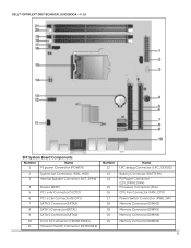
DELL™ OPTIPLEX™ 990 TECHNICAL GUIDEBOOK -V 1.0
SFF System Board Components
Number
Name
1
P1 power Connector (POWER)
2
System fan Connector (FAN_HDD)
3
Internal Speaker Connector (INT_SPKR)
4
Buzzer (BEEP)
5
PCI-e 4x Connector(SLOT2)
6
PCI-e 16x Connector(SLOT1)
7
SATA 2 Connector(SATA2)
8
SATA 1 Connector(SATA1)
9
SATA 0 ...
Technical Guide - Page 9
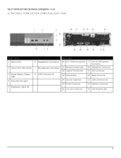
DELL™ OPTIPLEX™ 990 TECHNICAL GUIDEBOOK -V 1.0 ULTRA SMALL FORM FACTOR COMPUTER (USFF) VIEW
FRONT VIEW 1 Optical Drive
2 Optical Drive Eject Button
3 Power Button, Power Light
4 Drive Activity Light
5 Diagnostic Lights (4)
6 Headphone Connector 7 Microphone Connector 8 USB Connectors (2)
BACK VIEW
10 Wi-Fi Antenna (optional) 17 Line-in/ Microphone Connector
11 ...
Technical Guide - Page 10
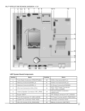
DELL™ OPTIPLEX™ 990 TECHNICAL GUIDEBOOK -V 1.0
USFF System Board Components
Number
Name
Number
Name
1
Front Panel Connector (FRONTPANEL)
10
SATA 1 Connector(SATA_1)
2
Memory Connector(DIMM_2)
11
SATA 0 Connector(SATA_0)
3
Memory Connector(DIMM_1)
12
P1 Power Connector(POWER1)
4
CPU Fan Connector (FAN_CPU)
13
HDD-ODD Power Connector (HDD_ODD_POWER)
5
Internal ...
Technical Guide - Page 14
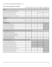
DELL™ OPTIPLEX™ 990 TECHNICAL GUIDEBOOK -V 1.0
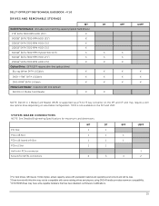
DRIVES AND REMOVABLE STORAGE
Bays: 5.25-inch Optical Bay Supported (External) Optical Drives Supported (maximum) Hard Drive Bay Supported (Internal)
MT
DT
2
1
2
1
2
1
Hard Drives Supported 3.5"/2.5" (maximum)
2/2
1/2
Interface:
SATA 2.0 ...
Technical Guide - Page 15
... to F3 bay converter on the MT and DT and may require a slim line optical drive depending on the SFF and USFF. DELL™ OPTIPLEX™ 990 TECHNICAL GUIDEBOOK -V 1.0
DRIVES AND REMOVABLE STORAGE
MT
DT
RAID 0 Performance: (includes two matching capacity/speed hard drives)
1TB1 SATA 7200 RPM HDD (3.5")
X
500GB1 SATA 7200 RPM HDD...
Technical Guide - Page 21

... BTU
N/A
Yes Yes Yes
Yes
21 DELL™ OPTIPLEX™ 990 TECHNICAL GUIDEBOOK -V 1.0 POWER
NOTE: These form factors utilize a more than one 12v rail) BTUs/h (based on Sine Wave output for APFC PSUs, not an approximation of a Sine Wave, Square Wave, or quasi-Square Wave.
Dell recommends only Universal Power Supplies (UPS) based on PSU max...
Technical Guide - Page 22

or Longer.1133Hrs.or Longer after 12 months.
22 DELL™ OPTIPLEX™ 990 TECHNICAL GUIDEBOOK -V 1.0 POWER
NOTE: These form factors utilize a more efficient Active Power Factor Correction (APFC) power supply. Dell recommends only Universal Power Supplies (UPS) based on Sine Wave output for APFC PSUs, not an approximation of a Sine Wave, Square Wave, or quasi-Square Wave. Continuous...
Similar Questions

How To Access The Front Power Button In Dell Precision 690 And Replace It?
The power button in my Dell Precision 690 workstation has fallen off the front panel and cannot be a...
The power button in my Dell Precision 690 workstation has fallen off the front panel and cannot be a...
(Posted by akm924 9 years ago)


Power Button Blinks When Switched On For Optiplex 990
(Posted by davdonn 10 years ago)
