
Biostar P4M80-M7 Support Question
Biostar P4M80-M7 Support Question
Find answers below for this question about Biostar P4M80-M7.Need a Biostar P4M80-M7 manual? We have 2 online manuals for this item!
Question posted by berniebu on May 12th, 2013
How Do You Remove Battery From Biostar P4m80m7?
The person who posted this question about this Biostar product did not include a detailed explanation. Please use the "Request More Information" button to the right if more details would help you to answer this question.
Current Answers
Answer #1: Posted by TommyKervz on May 13th, 2013 1:06 AM
TommyKervz

Member since:
January 10th, 2013 Points: 17,776,823

Member since:
January 10th, 2013 Points: 17,776,823
Greetings - Try pressing the metal clip away from the battery with your thumb and use a butter knife to plug the battery out (while the metal clicp is pressed away) - pushing the metal clip should release the bios battery and then easily plug it out of the socket.
Hope this helps
Related Biostar P4M80-M7 Manual Pages
P4M80-M7 user's manual - Page 1

... not occur in whole, is no representations or warranties with respect to the contents here and specially disclaims any implied warranties of their respective companies.
P4M80-M7
FCC Information and Copyright
This equipment has been tested and found in this user's manual. Duplication of this publication, in part or in a particular installation...
P4M80-M7 user's manual - Page 3

...1
Fan Speed Controller, !
Chipset North Bridge: VIA P4M800. Super I/O
Chip: ITE IT8705AF
Provides the most commonly used legacy super I/O functionality. Half/Full duplex capability. P4M80-M7
CHAPTER 1: INTRODUCTION
1.1 FEATURES
A. Supports 133/166/200MHz DDR devices. Environment Control initiatives: ! Front side bus at the following frequency ranges: - 533MT/s (133MHz Core Clock...
P4M80-M7 user's manual - Page 4

... RAID 0 and RAID 1 functions. Supports 2 serial ATA (SATA) ports. - Complaints with AC'97 Version 2.3 specification. Onboard IDE Support 4 IDE disk drives. Supports S/PDIF out function. P4M80-M7
Slot 3 PCI bus master slots. 1 AGP 4x/8x compatible slot. 1 CNR slot.
Front Side Onboard Peripherals 1 front panel header supports front panel facilities. 1 S/PDIF out...
P4M80-M7 user's manual - Page 5

Software Supports 9th TouchTM, FlasherTM, WinFlasherTM, and WarpspeederTM.
BIOS & Software
BIOS Award legal BIOS. P4M80-M7
Rear Side Connectors 4 USB 2.0 ports. 1 VGA port. 1 serial port. 1 parallel port. 1 RJ-45 LAN jack. 1 PS/2 Mouse & Keyboard port. 1 vertical audio port including 1 line-in ...
P4M80-M7 user's manual - Page 7

... Front panel audio out
O.
JCDIN1: CD-ROM audio in connector.
F. DIMM1/2: DDR memory modules. K. JPANEL1: front panel facilities header.
5 P4M80-M7
1.4 COMPONENTS
A
U
LGA775
T
CPU1
S B
P4M800
R
Super
I/O
C BIOS
LAN
Q P BAT1
D
E F
Codec
VT8237R O
N M L K
G
H
I . header. H. PCI1~3: Peripheral Component
S.
C. P. JSPDIFO1: Digital audio out connector...
P4M80-M7 user's manual - Page 8

... point wards this black cut edge on socket, and the white dot on the empty socket to a 90-degree angle. P4M80-M7
CHAPTER 2: HARDWARE INSTALLATION
2.1 CENTRAL PROCESSING UNIT (CPU) Special Notice:
Remove Pin Cap before installation, and make good preservation for the black cut edge. The CPU will fit only in the correct...
P4M80-M7 user's manual - Page 9

Step 2-2:
P4M80-M7
Step 3: Hold the CPU down firmly, and then close the lever to the JCFAN1. Connect the CPU FAN power cable to complete the installation.
This ...
P4M80-M7 user's manual - Page 10

MEMORY MODULE INSTALLATION
Unlock a DIMM slot by pressing the retaining clips outward.
P4M80-M7
2.3
1. Afterwards, plug in place and the DIMM is properly seated. Note:
To assure the system safety, if you need to change DDR modules, firstly, please ...
P4M80-M7 user's manual - Page 11
P4M80-M7
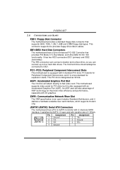
2.4 CONNECTORS AND SLOTS
FDD1: Floppy Disk Connector
The motherboard provides a standard floppy disk connector that provides PIO Mode 0~5, Bus Master, and Ultra DMA 33/ 66/ 100 functionality. AGP1: Accelerated Graphics Port Slot
Your monitor will take advantage of 1.5Gb/s. JSATA1/JSATA2: Serial ATA Connectors
The motherboard has a PCI to that video card. IDE1...
P4M80-M7 user's manual - Page 12

JUSBV2: JUSB3/4 are powered with +5V standby voltage. JUSBV1: JKBMS1, JUSB1 and
1
+5V Standby Pin 2-3 close ", if not, that means the jumper is "open".
P4M80-M7
CHAPTER 3: HEADERS & JUMPERS SETUP
3.1 HOW TO SETUP JUMPERS
The illustration shows how to support this function "Power-on system via keyboard and mouse", "JUSBV1/JUSBV2" ...
P4M80-M7 user's manual - Page 13

P4M80-M7
JATXPWR1/PATXPWR2: Power Connectors JATXPWR1: This connector allows user to connect the front audio out put cable with 20-pin power connector on back panel ...
P4M80-M7 user's manual - Page 14

Remove AC power line. 2. Power on pin2-3, it will record to avoid damaging the motherboard. JCI1: Chassis Open Header
This connector allows system ... for five seconds.
4. JCMOS1
Assignment
Pin 1-2 close
Clear CMOS data.
※ Clear CMOS Procedures:
1.
P4M80-M7
JCDIN1: CD-ROM Audio-in Connector
This connector allows user to connect the audio source from the veriaty devices...
P4M80-M7 user's manual - Page 15

It allows user to connect the PC case's front panel switch functions.
P4M80-M7
JPANEL1: Front Panel Header
This 24-pin connector includes Power-on button
IrDA Connector
13 PWR_LED
SLP
On/Off IR
++ -
2
24
1
+-
23
SPK
RST IR
...
P4M80-M7 user's manual - Page 16

Confirm motherboard model and download the respectively BIOS
from the Biostar
website: www.biostar.com.tw 3. Copy "AWDFLASH.exe" and respectively BIOS ...automatically and restart. 9. Make a bootable floppy disk. 2. Download the Flash Utility "AWDFLASH.exe" from Biostar website. 4. P4M80-M7
CHAPTER 4: USEFUL HELP
4.1 AWARD BIOS BEEP CODE
Beep Sound One long beep followed by virus, the ...
P4M80-M7 user's manual - Page 17

P4M80-M7 B. Remove the power cord from power supply for seconds. 3. Clear the CMOS data.
(See "Close CMOS Header: JCMOS1" section) 2. ... system again.
15 The CPU cooler surface is rotated normally. 3. CPU fan speed is over heated, the motherboard will shutdown automatically to relief the CPU protection function. 1. When the CPU is fulfilling with the CPU surface. 2. Or you can: ...
P4M80-M7 user's manual - Page 20

... just only for reference, the screen printed in this user manual will pop up. Please click "Next" button and follow the default procedure to your motherboard on hand.
18 INSTALLATION
Execute the setup execution file, and then the following dialog will change according to install.
2. P4M80-M7
5.3
1.
P4M80-M7 BIOS guide - Page 2
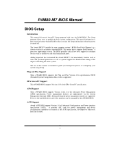
...-tuning of the EPA Green PC specification. This special information is then stored in battery-backed RAM so that it retains the Setup information when the power is intended to... Intel Pentium ® 4 processor input/output system. The rest of an industry standard BIOS. P4M80-M7 BIOS Manual
BIOS Setup
Introduction This manual discussed Award™ Setup program built into the ROM BIOS...
P4M80-M7 BIOS guide - Page 23

...), Disabled.
22 P4M80-M7 BIOS Manual
5.1 VIA OnChip IDE Device
The chipset contains a PCI IDE interface with support for faster drive access. Select "Enabled" to activate the first and/or second IDE interface. The Choices: Enabled (default), Disabled.
5.1.2 IDE DMA Transfer Access The Choices: Enabled (default), Disabled.
5.1.3
IDE Channel 0/1 The motherboard chipset contains...
P4M80-M7 BIOS guide - Page 30

...VGA BIOS to initialize the VGA card when system wakes up from S3 state . the motherboard battery (3V), the Power Supply (5VSB), and the Power Supply (3.3V). For example: ... lost . P4M80-M7 BIOS Manual
6.8 Modem Use IRQ This determines the IRQ, which can be used . When the Power Supply is lost when system is not supplying power, the motherboard uses the motherboard battery (3V). ...
P4M80-M7 BIOS guide - Page 37

...status during POST stage. This item only effective under Windows 98 ACPI mode.
8.2 CPU Vcore +3.3V, +5.0V, Voltage Battery Detect the system's voltage status automatically.
8.3 Current CPU Temp This field displays the current temperature of CPU.
8.4 Current ..., 70OC/158OF, Disabled (default).
36 The Choices: Disabled (Default), Enabled. Figure 8. P4M80-M7 BIOS Manual
8 PC Health Status
!
Similar Questions

Display Fades While Booting And Screen Becomes Dark. Motherboard P4m890-m7 Te
(Posted by shamnaarai 2 years ago)

Download Update For Motherboard G31d-m7 Ver 8.2
(Posted by Anonymous-155074 8 years ago)

Biostar P4m80-m7 Wattage?
What is the wattage of this mother board. I want to acquire a replacement supply for it.
What is the wattage of this mother board. I want to acquire a replacement supply for it.
(Posted by jlm14588 9 years ago)

8gb Ram On Motherboard G31 M7 V 6.5 Te
is there any way I can instal 8GB RAM on motherboard G31 M7 v 6.5 TE?
is there any way I can instal 8GB RAM on motherboard G31 M7 v 6.5 TE?
(Posted by placewithspace 10 years ago)

Download Audio Installers For Motherboard G31d-m7 Ver 8.2
(Posted by luctktlt 10 years ago)