Service Guide
Page 7
... the BIOS Utility 25 eMachines E627 BIOS 26 Information 26 Main 27 Security 28 Boot 31 Exit 32 BIOS Flash Utilities 33 DOS Flash Utility 34 WinFlash Utility 35 Remove HDD/BIOS Password Utilities 36 Machine Disassembly and Replacement 41 Disassembly Requirements 41 ...Pre-disassembly Instructions 42 Disassembly Process 42 External Module Disassembly Process 43 External Modules Disassembly Flowchart 43 Removing the Battery Pack 44 Removing the SD Dummy Card 45 Removing...
... the BIOS Utility 25 eMachines E627 BIOS 26 Information 26 Main 27 Security 28 Boot 31 Exit 32 BIOS Flash Utilities 33 DOS Flash Utility 34 WinFlash Utility 35 Remove HDD/BIOS Password Utilities 36 Machine Disassembly and Replacement 41 Disassembly Requirements 41 ...Pre-disassembly Instructions 42 Disassembly Process 42 External Module Disassembly Process 43 External Modules Disassembly Flowchart 43 Removing the Battery Pack 44 Removing the SD Dummy Card 45 Removing...
Service Guide
Page 8
... Power Board 104 Replacing the Upper Cover 104 Replacing the LCD Module 108 Replacing the Keyboard 113 Replacing the Switch Cover 114 Replacing the Hard Disk Drive Module 114 Replacing the WLAN Module 116 Replacing the DIMM Modules 116 Replacing the ODD Module 117 Replacing the Lower Covers 117 Replacing the SD Dummy Card 118 Replacing the Battery 119 Troubleshooting 121 Common...
... Power Board 104 Replacing the Upper Cover 104 Replacing the LCD Module 108 Replacing the Keyboard 113 Replacing the Switch Cover 114 Replacing the Hard Disk Drive Module 114 Replacing the WLAN Module 116 Replacing the DIMM Modules 116 Replacing the ODD Module 117 Replacing the Lower Covers 117 Replacing the SD Dummy Card 118 Replacing the Battery 119 Troubleshooting 121 Common...
Service Guide
Page 52
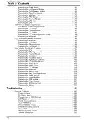
... 86.N2802.003 SCREW M2*3 17 86.N2802.004 SCREW M3*3 4 86.N2802.005 42 Chapter 3 Remove the battery pack. Place the system on a flat, stable surface. 4. Disassembly Process IMPORTANT: The LCD Module cannot be replaced. Observe the order of the sequence to avoid damage to any part of the hardware components.
... 86.N2802.003 SCREW M2*3 17 86.N2802.004 SCREW M3*3 4 86.N2802.005 42 Chapter 3 Remove the battery pack. Place the system on a flat, stable surface. 4. Disassembly Process IMPORTANT: The LCD Module cannot be replaced. Observe the order of the sequence to avoid damage to any part of the hardware components.
Service Guide
Page 83
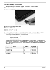
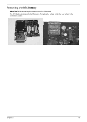
The RTC Battery is soldered to the connections shown. To replace the battery, solder the new battery to the Mainboard. Chapter 3 73 Removing the RTC Battery IMPORTANT:Follow local regulations for disposal of all batteries.
The RTC Battery is soldered to the connections shown. To replace the battery, solder the new battery to the Mainboard. Chapter 3 73 Removing the RTC Battery IMPORTANT:Follow local regulations for disposal of all batteries.
Service Guide
Page 129
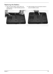
Replacing the Battery 1. Slide and hold the battery release latch to secure the battery in place. 2 1 Chapter 3 119 Slide the battery lock in the direction shown to the release position (1), insert the battery pack and press down (2). 2.
Replacing the Battery 1. Slide and hold the battery release latch to secure the battery in place. 2 1 Chapter 3 119 Slide the battery lock in the direction shown to the release position (1), insert the battery pack and press down (2). 2.
Service Guide
Page 133
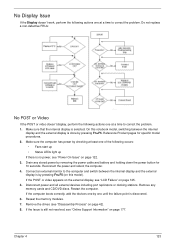
...this model). Make sure the computer has power by checking at least one of the following actions one by removing the power cable and battery and holding down the power button for specific model procedures. 2. Restart the computer. If the computer boots correctly, add the devices one ...modules. 7. Disconnect power and all external devices including port replicators or docking stations. Make sure that the internal display is discovered. 6. Do not replace a non-defective FRUs: No POST or Video If the POST or video doesn't display, perform the following occurs: • Fans start up...
...this model). Make sure the computer has power by checking at least one of the following actions one by removing the power cable and battery and holding down the power button for specific model procedures. 2. Restart the computer. If the computer boots correctly, add the devices one ...modules. 7. Disconnect power and all external devices including port replicators or docking stations. Make sure that the internal display is discovered. 6. Do not replace a non-defective FRUs: No POST or Video If the POST or video doesn't display, perform the following occurs: • Fans start up...
Service Guide
Page 134
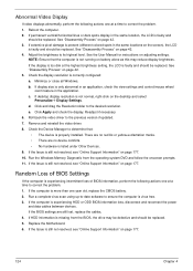
...right-click on page 42. 3. If desktop display resolution is properly installed. e. If the computer is correctly configured: a. Replace the Motherboard. 6. If the Issue is not running on page 177. 10. See "Disassembly Process" on the desktop and ... to determine that the computer is still not resolved, see "Online Support Information" on battery alone as this may be defective and should be replaced. 5. If the Issue is still not resolved, see "Online Support Information" on the... highest level. If HDD information is more than one year old, replace the CMOS battery. 2.
...right-click on page 42. 3. If desktop display resolution is properly installed. e. If the computer is correctly configured: a. Replace the Motherboard. 6. If the Issue is not running on page 177. 10. See "Disassembly Process" on the desktop and ... to determine that the computer is still not resolved, see "Online Support Information" on battery alone as this may be defective and should be replaced. 5. If the Issue is still not resolved, see "Online Support Information" on the... highest level. If HDD information is more than one year old, replace the CMOS battery. 2.
Service Guide
Page 143
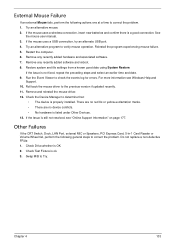
... and associated software. 7. There are no red Xs or yellow exclamation marks. • There are no device conflicts. • No hardware is ok. 3. Do not replace a non-defective FRUs: 1. Check Test Fixture is listed under Other Devices. 13. See the mouse user manual. 3. Restart the computer. 6. Restore system and file settings.... 2. External Mouse Failure If an external Mouse fails, perform the following general steps to correct the problem. 1. If the mouse uses a wireless connection, insert new batteries and confirm there is a good connection.
... and associated software. 7. There are no red Xs or yellow exclamation marks. • There are no device conflicts. • No hardware is ok. 3. Do not replace a non-defective FRUs: 1. Check Test Fixture is listed under Other Devices. 13. See the mouse user manual. 3. Restart the computer. 6. Restore system and file settings.... 2. External Mouse Failure If an external Mouse fails, perform the following general steps to correct the problem. 1. If the mouse uses a wireless connection, insert new batteries and confirm there is a good connection.
Service Guide
Page 144
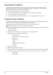
... no more errors. Rerun the test to verify that there are supported by a variety of reasons that all of the failure is detected, replace the FRU. If any problems are incorrect, whether a short circuit is suspected, or whether the system is detected, do with a hardware defect... to isolate the failing FRU (do the following devices: • Non-Acer devices • Printer, mouse, and other external devices • Battery pack • Hard disk drive • DIMM • CD-ROM/Diskette drive Module • PC Cards 4. Intermittent Problems Intermittent system hang problems...
... no more errors. Rerun the test to verify that there are supported by a variety of reasons that all of the failure is detected, replace the FRU. If any problems are incorrect, whether a short circuit is suspected, or whether the system is detected, do with a hardware defect... to isolate the failing FRU (do the following devices: • Non-Acer devices • Printer, mouse, and other external devices • Battery pack • Hard disk drive • DIMM • CD-ROM/Diskette drive Module • PC Cards 4. Intermittent Problems Intermittent system hang problems...
Service Guide
Page 189
A AFLASH Utility 33 Antennas Removing 86 Replacing 89 B Battery Replacing 119 Battery Pack Removing 44 BIOS ROM type 18 vendor 17 Version 17 BIOS Utility 25-33 Boot 31 Exit 32 Navigating 25 Onboard Device Configuration 29 ...Save and Exit 32 Security 28 System Security 32 Board Layout Top View 139 brightness hotkeys 14 C Camera Module Removing 81 Replacing 94 caps lock...
A AFLASH Utility 33 Antennas Removing 86 Replacing 89 B Battery Replacing 119 Battery Pack Removing 44 BIOS ROM type 18 vendor 17 Version 17 BIOS Utility 25-33 Boot 31 Exit 32 Navigating 25 Onboard Device Configuration 29 ...Save and Exit 32 Security 28 System Security 32 Board Layout Top View 139 brightness hotkeys 14 C Camera Module Removing 81 Replacing 94 caps lock...

Service Guide
Page 190
... P Panel 5 Bottom 8 PC Card 10 Power Board Removing 65 Replacing 104 Power On Failure 122 R Right Speaker Module Removing 68 Replacing 102 RTC Battery Removing 73 S SD Dummy Card Removing 45 Replacing 118 Speakers Removing 66, 68 speakers hotkey 14 Switch Cover Removing 55 Replacing 114 System Block Diagram 4 T Test Compatible Components 173 Thermal Module...
... P Panel 5 Bottom 8 PC Card 10 Power Board Removing 65 Replacing 104 Power On Failure 122 R Right Speaker Module Removing 68 Replacing 102 RTC Battery Removing 73 S SD Dummy Card Removing 45 Replacing 118 Speakers Removing 66, 68 speakers hotkey 14 Switch Cover Removing 55 Replacing 114 System Block Diagram 4 T Test Compatible Components 173 Thermal Module...


