User Guide
Page 1
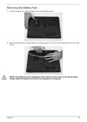
Removing the Battery Pack 1. Please detach the battery and follow local regulations for disposal. Slide and hold the battery release latch to the release position (1), then lift out the battery pack from the main unit (2). 2 1 NOTE: The battery has been highlighted with a yellow oval as shown in the direction shown. 2. Slide the battery lock in the above image. Turn the computer over. Chapter 3 53
Removing the Battery Pack 1. Please detach the battery and follow local regulations for disposal. Slide and hold the battery release latch to the release position (1), then lift out the battery pack from the main unit (2). 2 1 NOTE: The battery has been highlighted with a yellow oval as shown in the direction shown. 2. Slide the battery lock in the above image. Turn the computer over. Chapter 3 53
User Guide
Page 2
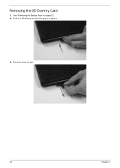
Push the SD dummy card all the way in to eject it out from the slot. 54 Chapter 3 Pull it . 3. Removing the SD Dummy Card 1. See "Removing the Battery Pack" on page 53. 2.
Push the SD dummy card all the way in to eject it out from the slot. 54 Chapter 3 Pull it . 3. Removing the SD Dummy Card 1. See "Removing the Battery Pack" on page 53. 2.
User Guide
Page 3
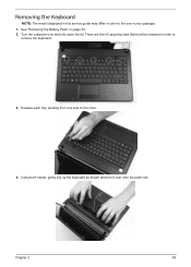
Turn the computer over onto the palm rest. There are five (5) securing clips that must be released in order to the other. 4. Release each clip, working from one in your package. 1. Chapter 3 55 Using both hands, gently pry up the keyboard as shown and turn it over and fully open the lid. See "Removing the Battery Pack" on page 53. 2. Removing the Keyboard NOTE: The model displayed in this service guide may differ in color to the one side to remove the keyboard. 3.
Turn the computer over onto the palm rest. There are five (5) securing clips that must be released in order to the other. 4. Release each clip, working from one in your package. 1. Chapter 3 55 Using both hands, gently pry up the keyboard as shown and turn it over and fully open the lid. See "Removing the Battery Pack" on page 53. 2. Removing the Keyboard NOTE: The model displayed in this service guide may differ in color to the one side to remove the keyboard. 3.

User Guide
Page 5
Removing the ODD Module 1. Remove the one (1) screw securing the ODD module in place. Screw Type Chapter 3 57 See "Removing the Battery Pack" on page 53. 2. Grasp the ODD by the bezel and slide it out of the chassis. Step ODD Module Disassembly Size M2.5*6.5 Quantity 1 3.
Removing the ODD Module 1. Remove the one (1) screw securing the ODD module in place. Screw Type Chapter 3 57 See "Removing the Battery Pack" on page 53. 2. Grasp the ODD by the bezel and slide it out of the chassis. Step ODD Module Disassembly Size M2.5*6.5 Quantity 1 3.

User Guide
Page 7
Main Unit Disassembly Process Main Unit Disassembly Flowchart NOTE: Use the process highlighted in red to access the Bluetooth module Screw List Step Lower Cover Battery Bay WLAN Module Disassembly USB Module Disassembly HDD Module Screw M2.5*6.5 M2.0*3.0 M2.0*3.0 M2.5*4.0 M2-0.4*2 Quantity 17 6 1 1 1 Part No. 86.ARE07.001 86.ARE07.002 86.ARE07.002 86.ARE07.002 86.W4107.002 Chapter 3 59
Main Unit Disassembly Process Main Unit Disassembly Flowchart NOTE: Use the process highlighted in red to access the Bluetooth module Screw List Step Lower Cover Battery Bay WLAN Module Disassembly USB Module Disassembly HDD Module Screw M2.5*6.5 M2.0*3.0 M2.0*3.0 M2.5*4.0 M2-0.4*2 Quantity 17 6 1 1 1 Part No. 86.ARE07.001 86.ARE07.002 86.ARE07.002 86.ARE07.002 86.W4107.002 Chapter 3 59

User Guide
Page 8
Remove the twenty three (23) securing screws from the lower cover. Part No. 86.N1407.007 86.ARE07.001 86.R6Z07.001 86.R6Z07.001 Step Lower Cover (red callout) Battery Bay (green callout) Size M2.5*6.5 M2.0*3.0 Quantity 17 6 Screw Type 60 Chapter 3 Step HDD Carrier Disassembly LCD Module Disassembly Thermal Module Disassembly Mainboard Disassembly Screw M3.0*3.5 M2.5*6.5 M2.5*4.0 M2.5*4.0 Quantity 4 4 1 1 Removing the Lower Cover 1. See "External Modules Disassembly Process" on page 52. 2.
Remove the twenty three (23) securing screws from the lower cover. Part No. 86.N1407.007 86.ARE07.001 86.R6Z07.001 86.R6Z07.001 Step Lower Cover (red callout) Battery Bay (green callout) Size M2.5*6.5 M2.0*3.0 Quantity 17 6 Screw Type 60 Chapter 3 Step HDD Carrier Disassembly LCD Module Disassembly Thermal Module Disassembly Mainboard Disassembly Screw M3.0*3.5 M2.5*6.5 M2.5*4.0 M2.5*4.0 Quantity 4 4 1 1 Removing the Lower Cover 1. See "External Modules Disassembly Process" on page 52. 2.

User Guide
Page 10
See "Removing the Lower Cover" on page 60. 2. This section is an overview of the major components of the main unit. 1 23 9 8 Item 1 2 3 4 5 Description RTC battery LVDS cable Thermal module WLAN module DIMM module(s) 76 5 4 Item 6 7 8 9 Description CPU Bluetooth cable HDD USB module 62 Chapter 3 Disassembly Overview 1.
See "Removing the Lower Cover" on page 60. 2. This section is an overview of the major components of the main unit. 1 23 9 8 Item 1 2 3 4 5 Description RTC battery LVDS cable Thermal module WLAN module DIMM module(s) 76 5 4 Item 6 7 8 9 Description CPU Bluetooth cable HDD USB module 62 Chapter 3 Disassembly Overview 1.
User Guide
Page 15
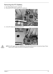
Lift the RTC battery away from the mainboard. 3. Chapter 3 67 NOTE: The RTC battery has been highlighted with the yellow circle as shown in the previous image. See "Disassembly Overview" on page 62. 2. Disconnect the RTC battery cable from the mainboard. Removing the RTC Battery 1. Please detach the RTC battery and follow local regulations for disposal.
Lift the RTC battery away from the mainboard. 3. Chapter 3 67 NOTE: The RTC battery has been highlighted with the yellow circle as shown in the previous image. See "Disassembly Overview" on page 62. 2. Disconnect the RTC battery cable from the mainboard. Removing the RTC Battery 1. Please detach the RTC battery and follow local regulations for disposal.
User Guide
Page 55
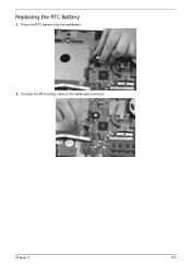
Connect the RTC battery cable to the mainboard connector. Place the RTC battery onto the mainboard. 2. Replacing the RTC Battery 1. Chapter 3 107
Connect the RTC battery cable to the mainboard connector. Place the RTC battery onto the mainboard. 2. Replacing the RTC Battery 1. Chapter 3 107
User Guide
Page 60
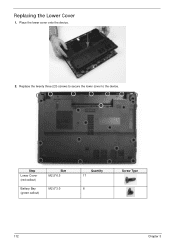
Replace the twenty three (23) screws to secure the lower cover to the device. Step Lower Cover (red callout) Battery Bay (green callout) Size M2.5*6.5 M2.0*3.0 Quantity 17 6 Screw Type 112 Chapter 3 Place the lower cover onto the device. 2. Replacing the Lower Cover 1.
Replace the twenty three (23) screws to secure the lower cover to the device. Step Lower Cover (red callout) Battery Bay (green callout) Size M2.5*6.5 M2.0*3.0 Quantity 17 6 Screw Type 112 Chapter 3 Place the lower cover onto the device. 2. Replacing the Lower Cover 1.
User Guide
Page 65
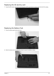
Chapter 3 117 Insert the battery pack and press down. 2. Slide the battery lock in the direction shown to secure the battery in place. Replacing the SD dummy card 1. Insert the SD dummy card into the slot and push until the card clicks into place and is flush with the casing. Replacing the Battery Pack 1.
Chapter 3 117 Insert the battery pack and press down. 2. Slide the battery lock in the direction shown to secure the battery in place. Replacing the SD dummy card 1. Insert the SD dummy card into the slot and push until the card clicks into place and is flush with the casing. Replacing the Battery Pack 1.


