eMachines Notebook User Guide (All Series)
Page 4
...; Slots and openings are used with a three-wire grounded plug. These openings must not exceed 80% of small children. This product should be blocked or covered.
...; Slots and openings are used with a three-wire grounded plug. These openings must not exceed 80% of small children. This product should be blocked or covered.
eMachines Notebook User Guide (All Series)
Page 5
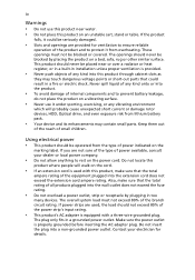
...exposed to temperatures over 60°C (140°F). Product servicing Do not attempt to service this product yourself, as opening or removing covers may expose you to qualified service personnel. If you come into the product • the product was spilled into Unplug this product... Using a power outlet that the new power cord meets the following the operating instructions Note: Adjust only those controls that are covered by the operating instructions, since improper adjustment of this product from unexpected noise produced by a qualified technician to restore the product...
...exposed to temperatures over 60°C (140°F). Product servicing Do not attempt to service this product yourself, as opening or removing covers may expose you to qualified service personnel. If you come into the product • the product was spilled into Unplug this product... Using a power outlet that the new power cord meets the following the operating instructions Note: Adjust only those controls that are covered by the operating instructions, since improper adjustment of this product from unexpected noise produced by a qualified technician to restore the product...
eMachines Notebook User Guide (All Series)
Page 12
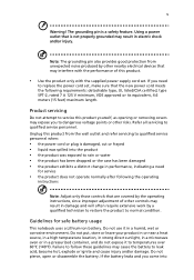
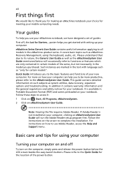
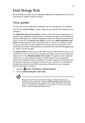
...the file requires Adobe Reader. Please refre to the eMachinesSystem User Guide. Quick Guide introduces you to thank you get started with language such as eMachines Recovery Management, using your computer Turning your computer on eMachinesSystem User Guide will occasionally refer to its nature, the Generic User Guide as well as... To turn on eMachinesSystem User Guide. xii First things first We would like to the basic features and functions of your new computer. It covers basic topics such as "only for the location of the power button. Your guides To help you purchased.
...the file requires Adobe Reader. Please refre to the eMachinesSystem User Guide. Quick Guide introduces you to thank you get started with language such as eMachines Recovery Management, using your computer Turning your computer on eMachinesSystem User Guide will occasionally refer to its nature, the Generic User Guide as well as... To turn on eMachinesSystem User Guide. xii First things first We would like to the basic features and functions of your new computer. It covers basic topics such as "only for the location of the power button. Your guides To help you purchased.
eMachines Notebook User Guide (All Series)
Page 30
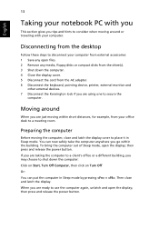
... the display. To bring the computer out of Sleep mode, open the display; If you may choose to shut down the computer. 4 Close the display cover. 5 Disconnect the cord from your computer. Moving around When you are just moving around or traveling with you This section gives you tips and hints... to consider when moving within the building. Then close and latch the display cover to use the computer again, unlatch and open the display; You can put the computer in Sleep mode.
... the display. To bring the computer out of Sleep mode, open the display; If you may choose to shut down the computer. 4 Close the display cover. 5 Disconnect the cord from your computer. Moving around When you are just moving around or traveling with you This section gives you tips and hints... to consider when moving within the building. Then close and latch the display cover to use the computer again, unlatch and open the display; You can put the computer in Sleep mode.
eMachines Notebook User Guide (All Series)
Page 31
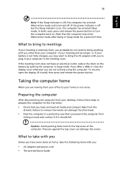
...), then press and release the power button. Caution: Avoid packing items next to your computer. Pressure against the top cover can prevent the computer from your office to the top cover of time. What to bring to meetings If your meeting will be longer, or if your battery is relatively short...not need to turn the computer back on , the computer has entered Sleep mode. Note that can damage the screen. Press + or close the display cover whenever you other than your home or vice versa. English 14 Note: If the Sleep indicator is off . If the power indicator is off but...
...), then press and release the power button. Caution: Avoid packing items next to your computer. Pressure against the top cover can prevent the computer from your office to the top cover of time. What to bring to meetings If your meeting will be longer, or if your battery is relatively short...not need to turn the computer back on , the computer has entered Sleep mode. Note that can damage the screen. Press + or close the display cover whenever you other than your home or vice versa. English 14 Note: If the Sleep indicator is off . If the power indicator is off but...
eMachines Notebook User Guide (All Series)
Page 37
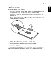
Please consult a qualified technician or contact your local eMachines dealer. English 20 Installing memory Follow these steps to access its base. 2 Remove the screws from the memory cover; then lift up and remove the memory cover. 3 (a) Insert the memory module diagonally into the slot, then (b) gently press it down until it... clicks into place. 4 Replace the memory cover and secure it with the screw. 5 Reinstall the battery pack, and reconnect the AC adapter. 6 Turn on the computer. The computer automatically...
Please consult a qualified technician or contact your local eMachines dealer. English 20 Installing memory Follow these steps to access its base. 2 Remove the screws from the memory cover; then lift up and remove the memory cover. 3 (a) Insert the memory module diagonally into the slot, then (b) gently press it down until it... clicks into place. 4 Replace the memory cover and secure it with the screw. 5 Reinstall the battery pack, and reconnect the AC adapter. 6 Turn on the computer. The computer automatically...
eMachines D620 Series Quick Guide
Page 3
poster helps you get started with language such as system utilities, data recovery, expansion options and troubleshooting. It covers basic topics such as the eMachinesSystem User Guide mentioned below will run the Adobe Reader setup program first. The Quick Guide ...etc. Such instances are only contained in certain models of guides: First off, the Just for Starters... If Adobe Reader is available in the eMachines product series. For more productive, please refer to the eMachinesSystem User Guide. Follow the instructions on how your notebook. It is not installed on...
poster helps you get started with language such as system utilities, data recovery, expansion options and troubleshooting. It covers basic topics such as the eMachinesSystem User Guide mentioned below will run the Adobe Reader setup program first. The Quick Guide ...etc. Such instances are only contained in certain models of guides: First off, the Just for Starters... If Adobe Reader is available in the eMachines product series. For more productive, please refer to the eMachinesSystem User Guide. Follow the instructions on how your notebook. It is not installed on...
eMachines D620 Series Quick Guide
Page 5
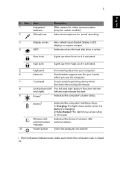
... when Num Lock is active. Fully charged: The light shows green when in AC mode. The front panel indicators are visible even when the computer cover is charging. 2. Num Lock Lights up .
... when Num Lock is active. Fully charged: The light shows green when in AC mode. The front panel indicators are visible even when the computer cover is charging. 2. Num Lock Lights up .
Service Guide
Page 6
These LOCALIZED FEATURES will not be covered in this generic service guide. vi add-on your regional web or channel. If, for whatever reason, a part number change is made, it supports, please ...
These LOCALIZED FEATURES will not be covered in this generic service guide. vi add-on your regional web or channel. If, for whatever reason, a part number change is made, it supports, please ...
Service Guide
Page 40
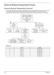
... Process External Modules Disassembly Flowchart The flowchart below gives you a graphic representation on the components that order. TURN OFF POWER AND PERIPHERALS Ax4 Bx1 LOWER COVER UNPLUG POWER CABLES Ex1 OPTICAL DISK DRIVE MODULE Cx2 WLAN BOARD DIMM MODULES HARD DISK DRIVE MODULE Fx1 OPTICAL LOCKER BRACKET OPTICAL DISK DRIVE HDD...
... Process External Modules Disassembly Flowchart The flowchart below gives you a graphic representation on the components that order. TURN OFF POWER AND PERIPHERALS Ax4 Bx1 LOWER COVER UNPLUG POWER CABLES Ex1 OPTICAL DISK DRIVE MODULE Cx2 WLAN BOARD DIMM MODULES HARD DISK DRIVE MODULE Fx1 OPTICAL LOCKER BRACKET OPTICAL DISK DRIVE HDD...
Service Guide
Page 41
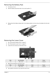
Removing the Battery Pack 1. Slide the battery lock/unlock latch to pry open the lower cover. See "Removing the Lower Cover" on page 51. 2. See "Removing the Battery Pack" on page 51. 3. Step 1~4 Size (Quantity) M2 x L4 (4) 4. Color Black Color Black Chapter 3 Torque 1.6 kgf-cm Torque... the battery release latch to the release position (2), then remove the battery from the main unit (3). Loosen the four screws (A) on the lower cover. Removing the Lower Cover 1. Remove the screw (B) on the lower cover. Turn base unit over. 2. Step Size (Quantity) 5 M2 x L18 (1) 5.
Removing the Battery Pack 1. Slide the battery lock/unlock latch to pry open the lower cover. See "Removing the Lower Cover" on page 51. 2. See "Removing the Battery Pack" on page 51. 3. Step 1~4 Size (Quantity) M2 x L4 (4) 4. Color Black Color Black Chapter 3 Torque 1.6 kgf-cm Torque... the battery release latch to the release position (2), then remove the battery from the main unit (3). Loosen the four screws (A) on the lower cover. Removing the Lower Cover 1. Remove the screw (B) on the lower cover. Turn base unit over. 2. Step Size (Quantity) 5 M2 x L18 (1) 5.
Service Guide
Page 42
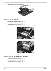
Remove the lower cover from the lower case. Removing the WLAN Board Modules 1. See "Removing the Battery Pack" on page 51. 4. See "Removing the Lower Cover" on page 51. 2. Do the same on page 51. 3. See "Removing the Lower Cover" on the other board. Remove the DIMM module. 6. See "Removing the Battery Pack" on page 51. 3. See "Removing the Lower Cover" on page 51. 2. Push out the latches on page 51. 52 Chapter 3 6. Removing the DIMM 1. See "Removing the Lower Cover" on both sides of the DIMM socket to release the DIMM. 5.
Remove the lower cover from the lower case. Removing the WLAN Board Modules 1. See "Removing the Battery Pack" on page 51. 4. See "Removing the Lower Cover" on page 51. 2. Do the same on page 51. 3. See "Removing the Lower Cover" on the other board. Remove the DIMM module. 6. See "Removing the Battery Pack" on page 51. 3. See "Removing the Lower Cover" on page 51. 2. Push out the latches on page 51. 52 Chapter 3 6. Removing the DIMM 1. See "Removing the Lower Cover" on both sides of the DIMM socket to release the DIMM. 5.
Service Guide
Page 44
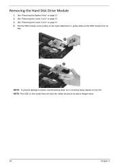
Pull the HDD module out by pulling on the mylar attached to device, avoid pressing down on it or placing heavy objects on top of it , gently slide-out the HDD module from its bay. NOTE: The HDD on page 51. 4. See "Removing the Lower Cover" on this model does not have the rubber enclosure as above images show. 54 Chapter 3 See "Removing the Lower Cover" on page 51. 2. See "Removing the Battery Pack" on page 51. 3. NOTE: To prevent damage to it . Removing the Hard Disk Drive Module 1.
Pull the HDD module out by pulling on the mylar attached to device, avoid pressing down on it or placing heavy objects on top of it , gently slide-out the HDD module from its bay. NOTE: The HDD on page 51. 4. See "Removing the Lower Cover" on this model does not have the rubber enclosure as above images show. 54 Chapter 3 See "Removing the Lower Cover" on page 51. 2. See "Removing the Battery Pack" on page 51. 3. NOTE: To prevent damage to it . Removing the Hard Disk Drive Module 1.
Service Guide
Page 46
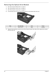
See "Removing the Lower Cover" on page 51. 2. Using the flat screwdriver, press the end of the unit. See "Removing the Battery Pack" on page 51. 3. See "Removing the Lower Cover" on the bottom side of the module forward, then slide out the optical drive module from the main unit. 56 Chapter 3 Removing the Optical Drive Module 1. Step 1 Size (Quantity) M2.5 x L6 (1) Color Black Torque 1.6 kgf-cm 5. Turn the base unit over, then remove the screw (E) on page 51. 4.
See "Removing the Lower Cover" on page 51. 2. Using the flat screwdriver, press the end of the unit. See "Removing the Battery Pack" on page 51. 3. See "Removing the Lower Cover" on the bottom side of the module forward, then slide out the optical drive module from the main unit. 56 Chapter 3 Removing the Optical Drive Module 1. Step 1 Size (Quantity) M2.5 x L6 (1) Color Black Torque 1.6 kgf-cm 5. Turn the base unit over, then remove the screw (E) on page 51. 4.
Service Guide
Page 48
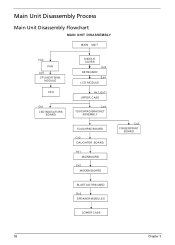
Main Unit Disassembly Process Main Unit Disassembly Flowchart MAIN UNIT DISASSEMBLY MAIN UNIT Hx2 FAN Ax5 CPU HEATSINK MODULE CPU Gx1 LED INDICATORS BOARD MIDDLE COVER Cx2 KEYBOARD Ex4 LCD MODULE Ax1, Ex11 UPPER CASE Cx4 TOUCHPAD BRACKET ASSEMBLY TOUCHPAD BOARD Cx2 DAUGHTER BOARD Ax1 MAINBOARD Cx2 MODEM BOARD Cx2 FINGERPRINT BOARD BLUETOOTH BOARD Dx2 SPEAKER MODULES LOWER CASE 58 Chapter 3
Main Unit Disassembly Process Main Unit Disassembly Flowchart MAIN UNIT DISASSEMBLY MAIN UNIT Hx2 FAN Ax5 CPU HEATSINK MODULE CPU Gx1 LED INDICATORS BOARD MIDDLE COVER Cx2 KEYBOARD Ex4 LCD MODULE Ax1, Ex11 UPPER CASE Cx4 TOUCHPAD BRACKET ASSEMBLY TOUCHPAD BOARD Cx2 DAUGHTER BOARD Ax1 MAINBOARD Cx2 MODEM BOARD Cx2 FINGERPRINT BOARD BLUETOOTH BOARD Dx2 SPEAKER MODULES LOWER CASE 58 Chapter 3
Service Guide
Page 49
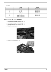
Detach the heatsink cable. Screw List A C D E G H Screw M2 x L4 M2 x L3 M3 x L4 M2.5 x L6 M2 x L3 M2.5 x L5 (torque 1.6) M2.5 x L5 (torque 3.0) Removing the Fan Module 1. See "Removing the Lower Cover" on page 51. 4. Chapter 3 59 See "Removing the Lower Cover" on page 51. 3. Detach the tin foil tape on page 51. 2. Part No. 86.00G64.720 86.9A552.3R0 86.9A524.4R0 86.00E33.736 86.00C07.220 86.00F87.735 5. See "Removing the Battery Pack" on the fan.
Detach the heatsink cable. Screw List A C D E G H Screw M2 x L4 M2 x L3 M3 x L4 M2.5 x L6 M2 x L3 M2.5 x L5 (torque 1.6) M2.5 x L5 (torque 3.0) Removing the Fan Module 1. See "Removing the Lower Cover" on page 51. 4. Chapter 3 59 See "Removing the Lower Cover" on page 51. 3. Detach the tin foil tape on page 51. 2. Part No. 86.00G64.720 86.9A552.3R0 86.9A524.4R0 86.00E33.736 86.00C07.220 86.00F87.735 5. See "Removing the Battery Pack" on the fan.
Service Guide
Page 50
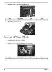
Step 1-2 Size (Quantity) M2.5 x L5 (2) 7. Unfasten the screws (A) securing the heatsink in the order shown. See "Removing the Lower Cover" on page 51. 2. Remove the screws (H) securing the fan to the main unit. Remove the fan from the main unit. 6. See "Removing the Battery Pack" on page 51. 3. Step 1-5 Size (Quantity) M2 x L4 (5) Color Silver Torque 1.6 kgf-cm 60 Chapter 3 Color Black Torque 1.6 kgf-cm Removing the CPU Heatsink Module 1. See "Removing the Fan Module" on page 59. 4.
Step 1-2 Size (Quantity) M2.5 x L5 (2) 7. Unfasten the screws (A) securing the heatsink in the order shown. See "Removing the Lower Cover" on page 51. 2. Remove the screws (H) securing the fan to the main unit. Remove the fan from the main unit. 6. See "Removing the Battery Pack" on page 51. 3. Step 1-5 Size (Quantity) M2 x L4 (5) Color Silver Torque 1.6 kgf-cm 60 Chapter 3 Color Black Torque 1.6 kgf-cm Removing the CPU Heatsink Module 1. See "Removing the Fan Module" on page 59. 4.
Service Guide
Page 51
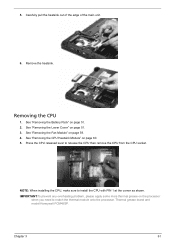
... page 51. 3. Thermal grease brand and model:Honeywell PCM45SP. Carefully pull the heatsink out of the edge of the main unit. 6. See "Removing the Lower Cover" on page 51. 2. IMPORTANT:To prevent any overheating problem, please apply some more thermal grease on page 60. 5. See "Removing the CPU Heatsink Module" on...
... page 51. 3. Thermal grease brand and model:Honeywell PCM45SP. Carefully pull the heatsink out of the edge of the main unit. 6. See "Removing the Lower Cover" on page 51. 2. IMPORTANT:To prevent any overheating problem, please apply some more thermal grease on page 60. 5. See "Removing the CPU Heatsink Module" on...
Service Guide
Page 52
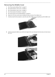
...under the side of the cover releases from the main unit, then remove the cover. 62 Chapter 3 See "Removing the Battery Pack" on page 59. 5. See "Removing the CPU Heatsink Module" on page 51. 4. Continue prying the middle cover until the full length of the middle cover and gently pry up ...the middle cover. 8. Open the LCD screen all the way to facilitate the easy removal of the middle...
...under the side of the cover releases from the main unit, then remove the cover. 62 Chapter 3 See "Removing the Battery Pack" on page 59. 5. See "Removing the CPU Heatsink Module" on page 51. 4. Continue prying the middle cover until the full length of the middle cover and gently pry up ...the middle cover. 8. Open the LCD screen all the way to facilitate the easy removal of the middle...
Service Guide
Page 53
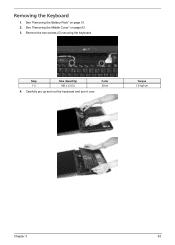
Remove the two screws (G) securing the keyboard. Step 1-2 Size (Quantity) M2 x L3 (2) 4. Carefully pry up and out the keyboard and turn it over. Color Silver Torque 1.6 kgf-cm Chapter 3 63 See "Removing the Battery Pack" on page 62. 3. See "Removing the Middle Cover" on page 51. 2. Removing the Keyboard 1.
Remove the two screws (G) securing the keyboard. Step 1-2 Size (Quantity) M2 x L3 (2) 4. Carefully pry up and out the keyboard and turn it over. Color Silver Torque 1.6 kgf-cm Chapter 3 63 See "Removing the Battery Pack" on page 62. 3. See "Removing the Middle Cover" on page 51. 2. Removing the Keyboard 1.


