

User Guide
Page 2
Every effort has been made to ensure that the information in your product firmware or your product due to differences in this book may differ slightly from your computer operating system. KEEP THIS GUIDE FOR FUTURE REFERENCE. Screenshots and graphics in this manual is accurate. 2 GS1100 Series User's Guide READ CAREFULLY BEFORE USE. IMPORTANT!
Every effort has been made to ensure that the information in your product firmware or your product due to differences in this book may differ slightly from your computer operating system. KEEP THIS GUIDE FOR FUTURE REFERENCE. Screenshots and graphics in this manual is accurate. 2 GS1100 Series User's Guide READ CAREFULLY BEFORE USE. IMPORTANT!

User Guide
Page 3
... 10 2.2.2 IEEE 802.3az EEE ...10 2.2.3 SFP Slots (GS1100-24 Only 10 2.2.4 Front Panel Connections ...12 2.2.5 Front Panel LEDs ...12 2.3 Hardware Installation ...14 2.3.1 Wall Mounting ...14 2.3.2 Rack Mounting ...15 2.3.3 Mounting the Switch on a Rack 16 Chapter 3 Troubleshooting...19 3.1 Improper Network Cabling and Topology 20 Appendix A Legal Information...21 Index ...23 GS1100 Series User's Guide 3
... 10 2.2.2 IEEE 802.3az EEE ...10 2.2.3 SFP Slots (GS1100-24 Only 10 2.2.4 Front Panel Connections ...12 2.2.5 Front Panel LEDs ...12 2.3 Hardware Installation ...14 2.3.1 Wall Mounting ...14 2.3.2 Rack Mounting ...15 2.3.3 Mounting the Switch on a Rack 16 Chapter 3 Troubleshooting...19 3.1 Improper Network Cabling and Topology 20 Appendix A Legal Information...21 Index ...23 GS1100 Series User's Guide 3

User Guide
Page 4
Table of Contents 4 GS1100 Series User's Guide
Table of Contents 4 GS1100 Series User's Guide

User Guide
Page 5
It can be used to build highperformance switched workgroup networks. This User's Guide covers the following models: GS1100-8HP, GS1100-16, GS1100-24, and GS110024E. The Switch is fanless and designed for workgroups, departments or backbone computing environments for uplink connection. The GS1100-24 has two SFP slots for small businesses. Use SFP transceivers in these slots for...
It can be used to build highperformance switched workgroup networks. This User's Guide covers the following models: GS1100-8HP, GS1100-16, GS1100-24, and GS110024E. The Switch is fanless and designed for workgroups, departments or backbone computing environments for uplink connection. The GS1100-24 has two SFP slots for small businesses. Use SFP transceivers in these slots for...

User Guide
Page 6
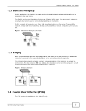
... providing 8000 MAC addresses entries. 1.3 Applications This section provides two network topology examples in which the Switch is used. 6 GS1100 Series User's Guide Chapter 1 Getting to Know Your Switch Figure 1 Front Panel GS1100-8HP GS1100-16 GS1100-24 GS1100-24E 1.2 Features The following are the essential features of the Switch. • Conforms to IEEE 802.3, 802.3u, 802...
... providing 8000 MAC addresses entries. 1.3 Applications This section provides two network topology examples in which the Switch is used. 6 GS1100 Series User's Guide Chapter 1 Getting to Know Your Switch Figure 1 Front Panel GS1100-8HP GS1100-16 GS1100-24 GS1100-24E 1.2 Features The following are the essential features of the Switch. • Conforms to IEEE 802.3, 802.3u, 802...
User Guide
Page 7
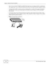
...print servers etc. The two networks (RD and Sales), the standalone server and the computers can be expected in an enterprise environment. GS1100 Series User's Guide 7 The Switch can all communicate with each other switches to the Switch. Figure 3 Bridging Example 1.4 Power Over Ethernet (PoE) ...The PoE function is an ideal solution for GS1100-8HP only. In this application, the Switch is an ideal solution for small networks where...
...print servers etc. The two networks (RD and Sales), the standalone server and the computers can be expected in an enterprise environment. GS1100 Series User's Guide 7 The Switch can all communicate with each other switches to the Switch. Figure 3 Bridging Example 1.4 Power Over Ethernet (PoE) ...The PoE function is an ideal solution for GS1100-8HP only. In this application, the Switch is an ideal solution for small networks where...
User Guide
Page 8
...Switch. Aside from minimizing the need for cables and wires, PoE removes the hassle of up to 30W per Switch. Figure 4 Powered Device Examples 8 GS1100 Series User's Guide A powered device (PD) is a device such as an access point or a switch, that it can supply power of trying to find a ...nearby electric outlet to the total PoE power budget per Ethernet port and up to power up devices. Chapter 1 Getting to Know Your Switch Ports 1 to 4 on the GS1100-8HP...
...Switch. Aside from minimizing the need for cables and wires, PoE removes the hassle of up to 30W per Switch. Figure 4 Powered Device Examples 8 GS1100 Series User's Guide A powered device (PD) is a device such as an access point or a switch, that it can supply power of trying to find a ...nearby electric outlet to the total PoE power budget per Ethernet port and up to power up devices. Chapter 1 Getting to Know Your Switch Ports 1 to 4 on the GS1100-8HP...

User Guide
Page 9
... Switch power on the rear panel of the Switch. Figure 5 Rear Panel GS1100-8HP GS1100-16 GS1100-24 GS1100-24E 2.1.1 Rear Panel Power Connection Connect one end of the Switch and the other end to the power receptacle on the panel. GS1100 Series User's Guide 9 Refer to the power supply requirements on the back of the supplied power...
... Switch power on the rear panel of the Switch. Figure 5 Rear Panel GS1100-8HP GS1100-16 GS1100-24 GS1100-24E 2.1.1 Rear Panel Power Connection Connect one end of the Switch and the other end to the power receptacle on the panel. GS1100 Series User's Guide 9 Refer to the power supply requirements on the back of the supplied power...

User Guide
Page 10
... connected device. You must use transceivers that comply with the exposed section of receive and transmit circuitry when it . 2.2.3 SFP Slots (GS1100-24 Only) These are auto-negotiating and auto-crossover. You can detect and adjust to the latency from the additional time required for the.... To avoid possible eye injury, do not look into power saving mode and switch off part of PCB board facing down. 10 GS1100 Series User's Guide An auto-negotiating port can change transceivers while the Switch is not transmitting or receiving data through or crossover Ethernet cable. 2.2.2 IEEE...
... connected device. You must use transceivers that comply with the exposed section of receive and transmit circuitry when it . 2.2.3 SFP Slots (GS1100-24 Only) These are auto-negotiating and auto-crossover. You can detect and adjust to the latency from the additional time required for the.... To avoid possible eye injury, do not look into power saving mode and switch off part of PCB board facing down. 10 GS1100 Series User's Guide An auto-negotiating port can change transceivers while the Switch is not transmitting or receiving data through or crossover Ethernet cable. 2.2.2 IEEE...

User Guide
Page 11
... transceiver's latch (latch styles vary). 3 Pull the transceiver out of the slot. Figure 8 Removing the Fiber Optic Cables Figure 9 Opening the Transceiver's Latch Example GS1100 Series User's Guide 11 Check the LEDs to verify that it clicks into place. 3 The Switch automatically detects the installed transceiver. Chapter 2 Hardware Description and Connection 2 Press the...
... transceiver's latch (latch styles vary). 3 Pull the transceiver out of the slot. Figure 8 Removing the Fiber Optic Cables Figure 9 Opening the Transceiver's Latch Example GS1100 Series User's Guide 11 Check the LEDs to verify that it clicks into place. 3 The Switch automatically detects the installed transceiver. Chapter 2 Hardware Description and Connection 2 Press the...

User Guide
Page 12
The following table describes the types of the LEDs. 12 GS1100 Series User's Guide Chapter 2 Hardware Description and Connection Figure 10 Transceiver Removal Example 2.2.4 Front Panel Connections You can use unshielded twisted pair (UTP) or shielded twisted-pair (STP) ...
The following table describes the types of the LEDs. 12 GS1100 Series User's Guide Chapter 2 Hardware Description and Connection Figure 10 Transceiver Removal Example 2.2.4 Front Panel Connections You can use unshielded twisted pair (UTP) or shielded twisted-pair (STP) ...

User Guide
Page 13
... speed. Figure 11 Front Panel LEDs GS1100-8HP GS1100-16 GS1100-24 GS1100-24E Chapter 2 Hardware Description and Connection The following table describes the LEDs. Off Power supplied to the PoE port(s) is not connected to an Ethernet network. Off Power is not supplied to the PoE port. GS1100 Series User's Guide 13 PoE MAX Red On Power...
... speed. Figure 11 Front Panel LEDs GS1100-8HP GS1100-16 GS1100-24 GS1100-24E Chapter 2 Hardware Description and Connection The following table describes the LEDs. Off Power supplied to the PoE port(s) is not connected to an Ethernet network. Off Power is not supplied to the PoE port. GS1100 Series User's Guide 13 PoE MAX Red On Power...
User Guide
Page 14
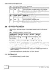
... on top of your Switch to a wall. 14 GS1100 Series User's Guide Off The Switch is receiving or transmitting data. LINK/ ACT Green On Blinking The port is connected to an Ethernet network. For GS1100-8HP, GS1100-16 and GS110-24E, you can place the Switch directly...mm space around it for a comparison of the hardware installation methods of each GS1100 model: Table 5 GS1100 Series Installation Comparison Table MODEL FEATURE Desktop Device Wall-mountable Rack-mountable GS1100-8HP GS1100-16 GS1100-24 GS1100-24E Note: Ask an authorized technician to attach the Switch to the rack/...
... on top of your Switch to a wall. 14 GS1100 Series User's Guide Off The Switch is receiving or transmitting data. LINK/ ACT Green On Blinking The port is connected to an Ethernet network. For GS1100-8HP, GS1100-16 and GS110-24E, you can place the Switch directly...mm space around it for a comparison of the hardware installation methods of each GS1100 model: Table 5 GS1100 Series Installation Comparison Table MODEL FEATURE Desktop Device Wall-mountable Rack-mountable GS1100-8HP GS1100-16 GS1100-24 GS1100-24E Note: Ask an authorized technician to attach the Switch to the rack/...
User Guide
Page 15
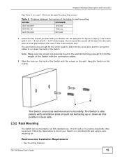
... holes on the back of the holes for wall mounting MODEL GS1100-8HP GS1100-16 DISTANCE 120 mm 148 mm GS1100-24E 207 mm 1 Screw the two screws provided with ventilation slots should be big enough for how far apart to the wall; GS1100 Series User's Guide 15 Chapter 2 Hardware Description and Connection See Table 6 on page...
... holes on the back of the holes for wall mounting MODEL GS1100-8HP GS1100-16 DISTANCE 120 mm 148 mm GS1100-24E 207 mm 1 Screw the two screws provided with ventilation slots should be big enough for how far apart to the wall; GS1100 Series User's Guide 15 Chapter 2 Hardware Description and Connection See Table 6 on page...

User Guide
Page 16
Failure to anchor the rack securely before installing the unit. Figure 12 Attaching the Mounting Brackets (GS1100-16 and GS1100-24E) Figure 13 Attaching the Mounting Brackets (GS1100-24) 2 Using a #2 Philips screwdriver, install the M3 flat head screws through the mounting bracket holes into the Switch....4 You may damage the unit. Precautions • Make sure the rack will safely support the combined weight of the rack. 16 GS1100 Series User's Guide Chapter 2 Hardware Description and Connection • Eight M3 flat head screws and a #2 Philips screwdriver. • Four M5 flat head...
Failure to anchor the rack securely before installing the unit. Figure 12 Attaching the Mounting Brackets (GS1100-16 and GS1100-24E) Figure 13 Attaching the Mounting Brackets (GS1100-24) 2 Using a #2 Philips screwdriver, install the M3 flat head screws through the mounting bracket holes into the Switch....4 You may damage the unit. Precautions • Make sure the rack will safely support the combined weight of the rack. 16 GS1100 Series User's Guide Chapter 2 Hardware Description and Connection • Eight M3 flat head screws and a #2 Philips screwdriver. • Four M5 flat head...

User Guide
Page 17
GS1100 Series User's Guide 17 Chapter 2 Hardware Description and Connection Figure 14 Mounting the Switch on a Rack (GS1100-16 and GS1100-24E) Figure 15 Mounting the Switch on a Rack (GS1100-24) 2 Using a #2 Philips screwdriver, install the M5 flat head screws through the mounting bracket holes into the rack. 3 Repeat steps 1 and 2 to attach the second mounting bracket on the other side of the rack.
GS1100 Series User's Guide 17 Chapter 2 Hardware Description and Connection Figure 14 Mounting the Switch on a Rack (GS1100-16 and GS1100-24E) Figure 15 Mounting the Switch on a Rack (GS1100-24) 2 Using a #2 Philips screwdriver, install the M5 flat head screws through the mounting bracket holes into the rack. 3 Repeat steps 1 and 2 to attach the second mounting bracket on the other side of the rack.

User Guide
Page 18
Chapter 2 Hardware Description and Connection 18 GS1100 Series User's Guide
Chapter 2 Hardware Description and Connection 18 GS1100 Series User's Guide
User Guide
Page 19
... Ethernet cables are connected properly and that you are using the supplied power cord and that you may encounter with the Switch and possible solutions. GS1100 Series User's Guide 19 The PoE LED is off and/or power is not being supplied to my PoE-enabled device. (For...
... Ethernet cables are connected properly and that you are using the supplied power cord and that you may encounter with the Switch and possible solutions. GS1100 Series User's Guide 19 The PoE LED is off and/or power is not being supplied to my PoE-enabled device. (For...
User Guide
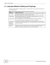
Page 20
Refer to Section 2.2.4 on page 12 for more than one path or route between two networked computers. This results in your network topology. 20 GS1100 Series User's Guide If you use longer cables than the limit of poor network performance or even network failure. Replace with new standard network cables. Non-standard cables ...
Refer to Section 2.2.4 on page 12 for more than one path or route between two networked computers. This results in your network topology. 20 GS1100 Series User's Guide If you use longer cables than the limit of poor network performance or even network failure. Replace with new standard network cables. Non-standard cables ...

User Guide
Page 21
... to change without the prior written permission of failure due to faulty workmanship and/or materials, ZyXEL will be required to the original end user (purchaser) that may cause undesired operations. These limits are designed to provide reasonable protection against harmful...or higher value, and will , at the discretion of God, or subjected to proper operating condition. GS1100 Series User's Guide 21 Published by an act of ZyXEL. Certifications Federal Communications Commission (FCC) Interference Statement This device complies with the instruction manual, may be ...
... to change without the prior written permission of failure due to faulty workmanship and/or materials, ZyXEL will be required to the original end user (purchaser) that may cause undesired operations. These limits are designed to provide reasonable protection against harmful...or higher value, and will , at the discretion of God, or subjected to proper operating condition. GS1100 Series User's Guide 21 Published by an act of ZyXEL. Certifications Federal Communications Commission (FCC) Interference Statement This device complies with the instruction manual, may be ...


