Brochure
Page 2
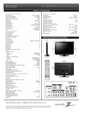
... x 400mm) POWER Consumption (Typical) 220W Stand-by Consumption RF 1080i/720p Digital Comb Filter ¥ (3D) Color Temperature Control 4 Modes Aspect Ratio Adjustment 6 Modes Enhanced Noise Reduction (Video Noise Filter) ¥ (3D & MPEG) Enhanced Line Doubler ¥ Picture Selection Mode 7 Modes Picture Reset ¥ DTV Signal Strength Indicator ¥ Black Stretcher (Black Level Enhancer) ¥ DB (Digital Booster) ¥ REAR AUDIO/VIDEO INPUTS/OUTPUTS RF In (Antenna/Cable) 1 L/R Audio/Component Video In...
... x 400mm) POWER Consumption (Typical) 220W Stand-by Consumption RF 1080i/720p Digital Comb Filter ¥ (3D) Color Temperature Control 4 Modes Aspect Ratio Adjustment 6 Modes Enhanced Noise Reduction (Video Noise Filter) ¥ (3D & MPEG) Enhanced Line Doubler ¥ Picture Selection Mode 7 Modes Picture Reset ¥ DTV Signal Strength Indicator ¥ Black Stretcher (Black Level Enhancer) ¥ DB (Digital Booster) ¥ REAR AUDIO/VIDEO INPUTS/OUTPUTS RF In (Antenna/Cable) 1 L/R Audio/Component Video In...
Operating Guide
Page 3
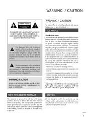
... one or more of important operating and maintenance (servicing) instructions in a particular installation. Increase the separation between the equipment and receiver. - Consult the dealer or an experienced radio/TV technician for compliance could void the user's authority to operate this product to radio or television reception, which the receiver is intended to alert the user to radio communications. CAUTION Do...
... one or more of important operating and maintenance (servicing) instructions in a particular installation. Increase the separation between the equipment and receiver. - Consult the dealer or an experienced radio/TV technician for compliance could void the user's authority to operate this product to radio or television reception, which the receiver is intended to alert the user to radio communications. CAUTION Do...
Operating Guide
Page 6
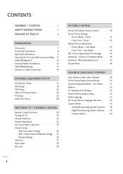
... - User Mode 43 - User Mode 44 DB - Preset 41 Color Tone - Preset 42 Manual Picture Adjustment - Color Tone - Analog Broadcasting System Captions 58 - Digital Broadcasting System Captions 59 - Channel Editing 36 Input List 37 Input Label 38 Key Lock 39 PICTURE CONTROL Picture Size (Aspect Ratio) Control 40 Preset Picture Settings - Auto Scan (Auto Tuning 34 - Picture Improvement Technology 45 Advanced - Black (Darkness) Level 47 Picture Reset 48 SOUND & LANGUAGE CONTROL Auto Volume Leveller (Auto Volume) 49 Preset Sound Setting (Sound Mode 50 Sound Setting...
... - User Mode 43 - User Mode 44 DB - Preset 41 Color Tone - Preset 42 Manual Picture Adjustment - Color Tone - Analog Broadcasting System Captions 58 - Digital Broadcasting System Captions 59 - Channel Editing 36 Input List 37 Input Label 38 Key Lock 39 PICTURE CONTROL Picture Size (Aspect Ratio) Control 40 Preset Picture Settings - Auto Scan (Auto Tuning 34 - Picture Improvement Technology 45 Advanced - Black (Darkness) Level 47 Picture Reset 48 SOUND & LANGUAGE CONTROL Auto Volume Leveller (Auto Volume) 49 Preset Sound Setting (Sound Mode 50 Sound Setting...
Operating Guide
Page 12
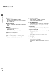
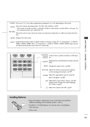
... (VIDEO) signal to the 1, 2 or 3 port with AC power. Note: In standby mode, these ports do not work. 8 AUDIO OUT Connect analog audio to this jack. Connect cable signals to various types of equipment. AUDIO (RGB/DVI) Connect the audio from an S-VIDEO device. 10 USB INPUT 11 Power Cord Socket For operation with a DVI to HDMI cable. 2 COMPONENT IN Connect a component video/audio device to the RS-232C port on DC power. 10 S-VIDEO Connect S-Video out from a PC or DTV. 4 REMOTE CONTROL PORT Connect your wired remote control. 5 RS-232C IN (CONTROL & SERVICE) PORT Connect...
... (VIDEO) signal to the 1, 2 or 3 port with AC power. Note: In standby mode, these ports do not work. 8 AUDIO OUT Connect analog audio to this jack. Connect cable signals to various types of equipment. AUDIO (RGB/DVI) Connect the audio from an S-VIDEO device. 10 USB INPUT 11 Power Cord Socket For operation with a DVI to HDMI cable. 2 COMPONENT IN Connect a component video/audio device to the RS-232C port on DC power. 10 S-VIDEO Connect S-Video out from a PC or DTV. 4 REMOTE CONTROL PORT Connect your wired remote control. 5 RS-232C IN (CONTROL & SERVICE) PORT Connect...

Operating Guide
Page 17
....00 15 I Select Component 1 input source by using the INPUT button on the remote control. How to connect I Turn on the digital set-top box. (Refer to the COMPONENT IN VIDEO 1 jacks on the set. Match the jack colors (Y = green, PB = blue, and PR = red). 2 Connect the audio output of the digital set top box to the owner's manual for the digital set -top box. Component Connection 1. COMPONENT IN 2 RS (CONTR 1 VIDEO AUDIO S-V ( ) 2. However, if you have finished connecting all equipment. How to use I /DVI IN RGB...
....00 15 I Select Component 1 input source by using the INPUT button on the remote control. How to connect I Turn on the digital set-top box. (Refer to the COMPONENT IN VIDEO 1 jacks on the set. Match the jack colors (Y = green, PB = blue, and PR = red). 2 Connect the audio output of the digital set top box to the owner's manual for the digital set -top box. Component Connection 1. COMPONENT IN 2 RS (CONTR 1 VIDEO AUDIO S-V ( ) 2. However, if you have finished connecting all equipment. How to use I /DVI IN RGB...

Operating Guide
Page 18
EXTERNAL EQUIPMENT SETUP EXTERNAL EQUIPMENT SETUP HDMI Connection 1. How to connect 1 Connect the digital set-top box to the owner's manual for the digital set . 2 No separated audio connection is necessary. HDMI supports both audio and video. ( ) 2. HDMI/DVI IN 3 2 RGB IN RGB(PC) AUDIO (RGB/DV COMPONENT IN 2 1 1 VIDEO 1 HDMI-DTV OUTPUT HDMI-DTV mode Resolution ...16 How to use I Turn on the digital set-top box. (Refer to HDMI/DVI IN1, 2 or 3 jack on the set -top box.) I Select HDMI1, HDMI2 or HDMI3 input source with using the INPUT button on the remote control.
EXTERNAL EQUIPMENT SETUP EXTERNAL EQUIPMENT SETUP HDMI Connection 1. How to connect 1 Connect the digital set-top box to the owner's manual for the digital set . 2 No separated audio connection is necessary. HDMI supports both audio and video. ( ) 2. HDMI/DVI IN 3 2 RGB IN RGB(PC) AUDIO (RGB/DV COMPONENT IN 2 1 1 VIDEO 1 HDMI-DTV OUTPUT HDMI-DTV mode Resolution ...16 How to use I Turn on the digital set-top box. (Refer to HDMI/DVI IN1, 2 or 3 jack on the set -top box.) I Select HDMI1, HDMI2 or HDMI3 input source with using the INPUT button on the remote control.

Operating Guide
Page 19
... HDMI3 input source with using the INPUT button on the digital set-top box. (Refer to the owner's manual for the digital set . 2. How to connect 1 Connect the DVI output of the digital set-top box to the HDMI/DVI IN1, 2 or 3 jack on the set. 2 Connect the audio output of the digital set-top box to HDMI Connection HDMI/DVI IN 3 2 RGB IN RGB(PC) AUDIO (RGB/DVI) COMPONENT IN 2 1 1 VIDEO AUDIO ANTENNA/ CABLE IN REMOTE DIGITAL AUDIO OUT CONTROL IN OPTICAL COAXIAL RS-232C IN (CONTROL & SERVICE) AUDIO OUT S-VIDEO VIDEO (MONO) AUDIO 2 1 AV...
... HDMI3 input source with using the INPUT button on the digital set-top box. (Refer to the owner's manual for the digital set . 2. How to connect 1 Connect the DVI output of the digital set-top box to the HDMI/DVI IN1, 2 or 3 jack on the set. 2 Connect the audio output of the digital set-top box to HDMI Connection HDMI/DVI IN 3 2 RGB IN RGB(PC) AUDIO (RGB/DVI) COMPONENT IN 2 1 1 VIDEO AUDIO ANTENNA/ CABLE IN REMOTE DIGITAL AUDIO OUT CONTROL IN OPTICAL COAXIAL RS-232C IN (CONTROL & SERVICE) AUDIO OUT S-VIDEO VIDEO (MONO) AUDIO 2 1 AV...

Operating Guide
Page 21
... DVD player's manual for operating instructions. HDMI/DVI IN 3 2 RGB IN RGB(PC) AUDIO (RGB/DVI COMPONENT IN 2 1 1 VIDEO A 1 HDMI-DVD OUTPUT 19 S-VIDEO AUDIO L R UDIO B/DVI) T IN ANTENNA/ CABLE IN 1 2 REMOTE DIGITAL AUDIO OUT CONTROL IN OPTICAL COAXIAL RS-232C IN (CONTROL & SERVICE) AUDIO OUT AUDIO S-VIDEO VIDEO (MONO) AUDIO AV IN 1 HDMI Connection 1. I Turn on the DVD player, insert a DVD. I Refer to AV IN2, select A V 2 input source. I Select A V 1 input source by using the INPUT button on the set . 2 Connect the audio outputs of the DVD to the AUDIO input...
... DVD player's manual for operating instructions. HDMI/DVI IN 3 2 RGB IN RGB(PC) AUDIO (RGB/DVI COMPONENT IN 2 1 1 VIDEO A 1 HDMI-DVD OUTPUT 19 S-VIDEO AUDIO L R UDIO B/DVI) T IN ANTENNA/ CABLE IN 1 2 REMOTE DIGITAL AUDIO OUT CONTROL IN OPTICAL COAXIAL RS-232C IN (CONTROL & SERVICE) AUDIO OUT AUDIO S-VIDEO VIDEO (MONO) AUDIO AV IN 1 HDMI Connection 1. I Turn on the DVD player, insert a DVD. I Refer to AV IN2, select A V 2 input source. I Select A V 1 input source by using the INPUT button on the set . 2 Connect the audio outputs of the DVD to the AUDIO input...

Operating Guide
Page 22
... VCR owner's manual.) 20 ( ) Antenna Connection GB IN AUDIO (RGB/DVI) MPONENT IN ANTENNA/ CABLE IN REMOTE DIGITAL AUDIO OUT CONTROL IN OPTICAL COAXIAL RS-232C IN (CONTROL & SERVICE) AUDIO OUT EO AUDIO S-VIDEO VIDEO (MONO) AUDIO AV IN 1 1 ANT OUT S-VIDEO VIDEO L R ANT IN OUTPUT SWITCH Wall Jack 2 Antenna 1. EXTERNAL EQUIPMENT SETUP EXTERNAL EQUIPMENT SETUP VCR SETUP I Use the ISM feature in the Option menu to avoid having a fixed image remain on the screen for a long period of time (Only Plasma TV model). If the 4:3 picture format...
... VCR owner's manual.) 20 ( ) Antenna Connection GB IN AUDIO (RGB/DVI) MPONENT IN ANTENNA/ CABLE IN REMOTE DIGITAL AUDIO OUT CONTROL IN OPTICAL COAXIAL RS-232C IN (CONTROL & SERVICE) AUDIO OUT EO AUDIO S-VIDEO VIDEO (MONO) AUDIO AV IN 1 1 ANT OUT S-VIDEO VIDEO L R ANT IN OUTPUT SWITCH Wall Jack 2 Antenna 1. EXTERNAL EQUIPMENT SETUP EXTERNAL EQUIPMENT SETUP VCR SETUP I Use the ISM feature in the Option menu to avoid having a fixed image remain on the screen for a long period of time (Only Plasma TV model). If the 4:3 picture format...

Operating Guide
Page 23
I If connected to AV IN2, select A V 2 input source. UDIO B/DVI) 2. AUDIO S-VIDEO VIDEO (MONO) AUDIO I If connected to AV IN2, select A V 2 input source. ! Match the jack colors (Video = yellow, Audio Left = white, and Audio Right = red) ANT OUT OUTPUT SWITCH 1 ANTENNA/ CABLE IN 2. UDIO B/DVI) T IN REMOTE DIGITAL AUDIO OUT CONTROL IN OPTICAL COAXIAL RS-232C IN (CONTROL & SERVICE) ( ) AUDIO OUT AUDIO S-VIDEO VIDEO (MONO) AUDIO ! NOTE G The picture quality is improved: compared to the AUDIO input jacks on the set. CAUTION G Do not connect to the AUDIO L/MONO...
I If connected to AV IN2, select A V 2 input source. UDIO B/DVI) 2. AUDIO S-VIDEO VIDEO (MONO) AUDIO I If connected to AV IN2, select A V 2 input source. ! Match the jack colors (Video = yellow, Audio Left = white, and Audio Right = red) ANT OUT OUTPUT SWITCH 1 ANTENNA/ CABLE IN 2. UDIO B/DVI) T IN REMOTE DIGITAL AUDIO OUT CONTROL IN OPTICAL COAXIAL RS-232C IN (CONTROL & SERVICE) ( ) AUDIO OUT AUDIO S-VIDEO VIDEO (MONO) AUDIO ! NOTE G The picture quality is improved: compared to the AUDIO input jacks on the set. CAUTION G Do not connect to the AUDIO L/MONO...
Operating Guide
Page 27
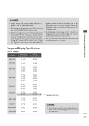
... best picture quality, adjust the PC graphics card to find best picture in PC mode. There may be noise associated with the resolution, vertical pattern, contrast or brightness in a little time. 25 EXTERNAL EQUIPMENT SETUP Supported Display Specifications RGB-PC, HDMI-PC Resolution ...fixed image may not work if a HDMI to another rate or adjust the brightness and contrast on the screen. NOTE G Depending on the graphics card, DOS mode may become permanently imprinted on the PICTURE menu until the picture is present, change the PC output to another resolution, change...
... best picture quality, adjust the PC graphics card to find best picture in PC mode. There may be noise associated with the resolution, vertical pattern, contrast or brightness in a little time. 25 EXTERNAL EQUIPMENT SETUP Supported Display Specifications RGB-PC, HDMI-PC Resolution ...fixed image may not work if a HDMI to another rate or adjust the brightness and contrast on the screen. NOTE G Depending on the graphics card, DOS mode may become permanently imprinted on the PICTURE menu until the picture is present, change the PC output to another resolution, change...

Operating Guide
Page 31
... DIO DVI) IN ANTENNA/ CABLE IN REMOTE DIGITAL AUDIO OUT CONTROL IN OPTICAL COAXIAL RS-232C IN (CONTROL & SERVICE) 1 AUDIO OUT AUDIO S-VIDEO VIDEO (MONO) AUDIO CAUTION 2 G Do not look into the optical output port. tion. ! EXTERNAL EQUIPMENT SETUP Digital ( ) 1. How to connect 1 Connect one end of the optical or coaxial cable to the TV's OPTICAL or COAXIAL port of DIGITAL AUDIO OUT. 2 Connect the other end of the optical or coaxial cable to the digital audio input on the audio equipment. 3 Set the "TV Speaker option -
... DIO DVI) IN ANTENNA/ CABLE IN REMOTE DIGITAL AUDIO OUT CONTROL IN OPTICAL COAXIAL RS-232C IN (CONTROL & SERVICE) 1 AUDIO OUT AUDIO S-VIDEO VIDEO (MONO) AUDIO CAUTION 2 G Do not look into the optical output port. tion. ! EXTERNAL EQUIPMENT SETUP Digital ( ) 1. How to connect 1 Connect one end of the optical or coaxial cable to the TV's OPTICAL or COAXIAL port of DIGITAL AUDIO OUT. 2 Connect the other end of the optical or coaxial cable to the digital audio input on the audio equipment. 3 Set the "TV Speaker option -
Operating Guide
Page 33
.... ADJUST Adjustment for type of another product is selected, a button on the viewing environment. I Close cover. 31 MODE Select the remote operating mode: TV, DVD, VCR, AUDIO, or STB. * If the mode of program. WATCHING TV / CHANNEL CONTROL 0 FLASHBK ADJUST RATIO PICTURE SOUND SAP CC VCR/DVD Control buttons Control video cassette recorders or DVD players. RATIO Change the aspect ratio. G p.57 Installing Batteries I Open the battery compartment cover on the mode. I Install two 1.5V AAA batteries. G p.40 PICTURE Adjust the factory preset picture...
.... ADJUST Adjustment for type of another product is selected, a button on the viewing environment. I Close cover. 31 MODE Select the remote operating mode: TV, DVD, VCR, AUDIO, or STB. * If the mode of program. WATCHING TV / CHANNEL CONTROL 0 FLASHBK ADJUST RATIO PICTURE SOUND SAP CC VCR/DVD Control buttons Control video cassette recorders or DVD players. RATIO Change the aspect ratio. G p.57 Installing Batteries I Open the battery compartment cover on the mode. I Install two 1.5V AAA batteries. G p.40 PICTURE Adjust the factory preset picture...

Operating Guide
Page 35
... Language Input Label Key Lock Caption Set ID : English : Off : Off : 1 AUDIO Sound Mode Auto Volume Balance TV Speaker : Standard : On : 0 : On TIME Clock Off Time On Time Sleep Time Auto Sleep : Oct 19, 2006, 03:44 AM : Off : Off : Off : Off 33 WATCHING TV / CHANNEL CONTROL ON-SCREEN MENUS SELECTION Your TV's OSD (On Screen Display) may differ slightly from what is shown in this manual. 1 Press the MENU button and then use or button to...
... Language Input Label Key Lock Caption Set ID : English : Off : Off : 1 AUDIO Sound Mode Auto Volume Balance TV Speaker : Standard : On : 0 : On TIME Clock Off Time On Time Sleep Time Auto Sleep : Oct 19, 2006, 03:44 AM : Off : Off : Off : Off 33 WATCHING TV / CHANNEL CONTROL ON-SCREEN MENUS SELECTION Your TV's OSD (On Screen Display) may differ slightly from what is shown in this manual. 1 Press the MENU button and then use or button to...
Operating Guide
Page 37
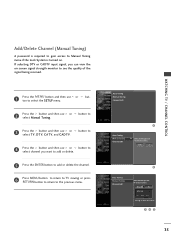
... is turned on -screen signal strength monitor to see the quality of the signal being received. 1 Press the MENU button and then use or select channel you can view the on . If selecting DTV or CADTV input signal, you want to 3 Press the button and then use select Manual Tuning. button to 4 Press the button and then use ton to delete the channel. 345 35 WATCHING TV / CHANNEL CONTROL Add/Delete Channel (Manual Tuning) A password...
... is turned on -screen signal strength monitor to see the quality of the signal being received. 1 Press the MENU button and then use or select channel you can view the on . If selecting DTV or CADTV input signal, you want to 3 Press the button and then use select Manual Tuning. button to 4 Press the button and then use ton to delete the channel. 345 35 WATCHING TV / CHANNEL CONTROL Add/Delete Channel (Manual Tuning) A password...
Operating Guide
Page 57
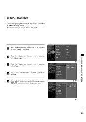
... Language Input Label Key Lock Caption ISM Method Low Power Front Display Set ID 23 Menu Audio English English 4 55 button to select : English, Spanish, or 5 Press MENU button to return to TV viewing or press RETURN button to return to select the OPTION menu. or button to select Audio. 4 Use or F r e n c h. AUDIO LANGUAGE Other languages may be available if a digital signal is provided by the broadcasting station. This feature operates...
... Language Input Label Key Lock Caption ISM Method Low Power Front Display Set ID 23 Menu Audio English English 4 55 button to select : English, Spanish, or 5 Press MENU button to return to TV viewing or press RETURN button to return to select the OPTION menu. or button to select Audio. 4 Use or F r e n c h. AUDIO LANGUAGE Other languages may be available if a digital signal is provided by the broadcasting station. This feature operates...
Operating Guide
Page 68
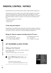
... categories to select the LOCK menu. I Enter the password as requested. To use this menu. 1 Press the MENU button and then use the Movie Rating System (MPAA) only. Most television programs and television movies can be done : 1. The default setting is to block specific channels, ratings, and external viewing sources. A password is set up blocking schemes to allow all program viewing for -TV movies : I TV-G (General audience) I TV-PG (Parental guidance suggested) I TV...
... categories to select the LOCK menu. I Enter the password as requested. To use this menu. 1 Press the MENU button and then use the Movie Rating System (MPAA) only. Most television programs and television movies can be done : 1. The default setting is to block specific channels, ratings, and external viewing sources. A password is set up blocking schemes to allow all program viewing for -TV movies : I TV-G (General audience) I TV-PG (Parental guidance suggested) I TV...

Operating Guide
Page 74
...'s power cord into wall power outlet? I Check your service center, if the picture has not appeared after five minutes. Please after switching on station tuned with correct polarity (+ to restore the brightness of the antenna). 72 I Station signal is turned on some channels I Test the wall power outlet, plug another station. I No broadcast on contact your antenna direction and/or location. I Ensure that the correct remote operating mode is...
...'s power cord into wall power outlet? I Check your service center, if the picture has not appeared after five minutes. Please after switching on station tuned with correct polarity (+ to restore the brightness of the antenna). 72 I Station signal is turned on some channels I Test the wall power outlet, plug another station. I No broadcast on contact your antenna direction and/or location. I Ensure that the correct remote operating mode is...

Operating Guide
Page 77
... code is successful. 4 Press the MENU button to operate the device. APPENDIX 75 The program- If you have to see if the device responds properly. PROGRAMMING THE REMOTE CONTROL The provided universal remote control can operate each device without programming, turn on the device (such as a VCR) and press the corresponding mode button on the remote. Note that , press the POWER button. When pressing the button, the light blinks at the same time...
... code is successful. 4 Press the MENU button to operate the device. APPENDIX 75 The program- If you have to see if the device responds properly. PROGRAMMING THE REMOTE CONTROL The provided universal remote control can operate each device without programming, turn on the device (such as a VCR) and press the corresponding mode button on the remote. Note that , press the POWER button. When pressing the button, the light blinks at the same time...
Operating Guide
Page 85
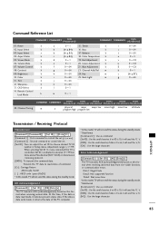
... At this model, TV will not send the status during the standby mode. * Data Format [Command 2] : Use as command. [Set ID] : Use the small character, if set ID is 10, it will send the 'a', 'b'. [OK] : Use the large character. Power k 02. Input Select k 03. Volume Mute k 07. Data1: Illegal Code Data2: Not supported function Data3: Wait more time * In this format when receiving normal data. Remote Control Lock Mode k a 0~1 15. Red Adjustment k e 0~1 20...
... At this model, TV will not send the status during the standby mode. * Data Format [Command 2] : Use as command. [Set ID] : Use the small character, if set ID is 10, it will send the 'a', 'b'. [OK] : Use the large character. Power k 02. Input Select k 03. Volume Mute k 07. Data1: Illegal Code Data2: Not supported function Data3: Wait more time * In this format when receiving normal data. Remote Control Lock Mode k a 0~1 15. Red Adjustment k e 0~1 20...


