
Operation Guide
Page 2
... and on a circuit different from LG Electronics. Connect the equipment to an outlet on , the user is connected. -Consult the dealer or an experienced radio/TV technician for compliance could void the user's authority to the point of the National Electric Code (U.S.A.). These limits are designed to modify this equipment does...
... and on a circuit different from LG Electronics. Connect the equipment to an outlet on , the user is connected. -Consult the dealer or an experienced radio/TV technician for compliance could void the user's authority to the point of the National Electric Code (U.S.A.). These limits are designed to modify this equipment does...

Operation Guide
Page 3
... shall be given in a language acceptable to the country where the apparatus is intended to be placed immediately adjacent to install TV by When mounting a TV it on or pinched particularly at plugs, convenience receptacles, and the point where they exit from being walked on the wall,... heat sources such as follows. Only use attachments/accessories the manufacturer, specified by hanging power and signal cables on the back of the TV. If the provided plug does not fit into your safety. Do not install near water. Heed all instructions. Install in accordance with each...
... shall be given in a language acceptable to the country where the apparatus is intended to be placed immediately adjacent to install TV by When mounting a TV it on or pinched particularly at plugs, convenience receptacles, and the point where they exit from being walked on the wall,... heat sources such as follows. Only use attachments/accessories the manufacturer, specified by hanging power and signal cables on the back of the TV. If the provided plug does not fit into your safety. Do not install near water. Heed all instructions. Install in accordance with each...

Operation Guide
Page 5
... Cable Connection 16 HD Receiver Setup 17 DVD Setup 20 VCR Setup 22 Headphone Setup 24 PC Setup 25 Remote Control Functions 28 Turning On TV 30 Channel Selection 30 Volume Adjustment 30 On-Screen Menus Selection 31 Channel Search -
... Cable Connection 16 HD Receiver Setup 17 DVD Setup 20 VCR Setup 22 Headphone Setup 24 PC Setup 25 Remote Control Functions 28 Turning On TV 30 Channel Selection 30 Volume Adjustment 30 On-Screen Menus Selection 31 Channel Search -
Operation Guide
Page 6
Auto Clock Setup 57 - Manual Clock Setup 58 Auto On/Off Time Setting 59 Sleep Time Setting 60 Auto Shut-off Setting 61 Set Password & Lock System 62 Movie & TV Rating 64 Troubleshooting 67 Maintenance 69 Product Specifications 70 5 Clock Setting -
Auto Clock Setup 57 - Manual Clock Setup 58 Auto On/Off Time Setting 59 Sleep Time Setting 60 Auto Shut-off Setting 61 Set Password & Lock System 62 Movie & TV Rating 64 Troubleshooting 67 Maintenance 69 Product Specifications 70 5 Clock Setting -

Operation Guide
Page 7
... monitor's performance. On Disposal a. b. Disposal of this product must be visible on . Some minute dot defects may be carried out in this product with TV. However, they have no adverse effect on the screen. Do not dispose of this product contains a small amount of mercury. Avoid touching the... LCD screen or holding your local authority. 6 c. The fluorescent lamp used in accordance to the touch, there may be a small "flicker" when it for long ...
... monitor's performance. On Disposal a. b. Disposal of this product must be visible on . Some minute dot defects may be carried out in this product with TV. However, they have no adverse effect on the screen. Do not dispose of this product contains a small amount of mercury. Avoid touching the... LCD screen or holding your local authority. 6 c. The fluorescent lamp used in accordance to the touch, there may be a small "flicker" when it for long ...
Operation Guide
Page 9
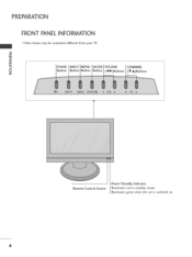
Illuminates green when the set is switched on. 8 PREPARATION FRONT PANELINFORMATION Here shown may be somewhat different from your TV. _o m _o vlENU VOLUME CHANNEL © z _utton (_1,1_)Buttons (V,A)Buttons Remote Control Sensor Power/Standby Indicator Illuminates red in standby mode.
Illuminates green when the set is switched on. 8 PREPARATION FRONT PANELINFORMATION Here shown may be somewhat different from your TV. _o m _o vlENU VOLUME CHANNEL © z _utton (_1,1_)Buttons (V,A)Buttons Remote Control Sensor Power/Standby Indicator Illuminates red in standby mode.

Operation Guide
Page 10
... jack with AC power. AV IN (Audio/Video) Connect audio/video output from an external device to these jacks. Caution: Never attempt to operate the TV on DC power. 9 Or DVI (Video) signal to this jack. @ RGB (PC)IN Connect the output from a PC. AUDIO IN (RGB/DVI) Connect the audio... over-the air signals to this jack. S-VIDEO Connect S-Video out from an S-VIDEO device. BACK PANELINFORMATION ,,,IHere shown may be somewhat different from your TV. -O m © z SERVICEONLY RS-232C IN (SERVICE ONLY) PORT For service. @ HDMI/DVI IN Connect a HDMI signal to this jack.
... jack with AC power. AV IN (Audio/Video) Connect audio/video output from an external device to these jacks. Caution: Never attempt to operate the TV on DC power. 9 Or DVI (Video) signal to this jack. @ RGB (PC)IN Connect the output from a PC. AUDIO IN (RGB/DVI) Connect the audio... over-the air signals to this jack. S-VIDEO Connect S-Video out from an S-VIDEO device. BACK PANELINFORMATION ,,,IHere shown may be somewhat different from your TV. -O m © z SERVICEONLY RS-232C IN (SERVICE ONLY) PORT For service. @ HDMI/DVI IN Connect a HDMI signal to this jack.

Operation Guide
Page 11
Insert the STAND BODY into a COVER BASE until clicking sound. STAND BODY COVER BASE 10 m Carefully place the product screen side down on a cushioned surface that will protect product and screen from your TV. Once assembled take the TV up carefully and face the front side. PREPARATION STAND INSTALLATION ""_Here shown may be somewhat different from damage. © z Assemble parts of the STAND BODY with COVER BASE of the stand.
Insert the STAND BODY into a COVER BASE until clicking sound. STAND BODY COVER BASE 10 m Carefully place the product screen side down on a cushioned surface that will protect product and screen from your TV. Once assembled take the TV up carefully and face the front side. PREPARATION STAND INSTALLATION ""_Here shown may be somewhat different from damage. © z Assemble parts of the STAND BODY with COVER BASE of the stand.
Operation Guide
Page 12
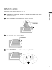
m @ Pull the COVER BASE backward while pressing button on a cushioned surface that will protect product and screen from damage. Carefully place the product screen side down on stand body. © z COVER BASE Hold the STAND BODY and bend it upward. DETACHING STAND Here shown may be somewhat different from set while pressing the 2 latches. 11 STAND BODY Pull the STAND BODY to separate from your TV.
m @ Pull the COVER BASE backward while pressing button on a cushioned surface that will protect product and screen from damage. Carefully place the product screen side down on stand body. © z COVER BASE Hold the STAND BODY and bend it upward. DETACHING STAND Here shown may be somewhat different from set while pressing the 2 latches. 11 STAND BODY Pull the STAND BODY to separate from your TV.

Operation Guide
Page 13
Hold the CABLE MANAGEMENT with both hands and pull it upward. 12 To connect an additional equipment, see the EXTERNAL EQUIPMENT SETUP section. _D © z Install the CABLE MANAGEMENT as necessary. me :ABLE MANAGEMENT How to remove the CABLE MANAGEMENT First, press the cable management. PREPARATION BACK COVERFORWIREARRANGEMENT ,,,_Here shown may be somewhat different from your TV. _D m Connect the cables as shown.
Hold the CABLE MANAGEMENT with both hands and pull it upward. 12 To connect an additional equipment, see the EXTERNAL EQUIPMENT SETUP section. _D © z Install the CABLE MANAGEMENT as necessary. me :ABLE MANAGEMENT How to remove the CABLE MANAGEMENT First, press the cable management. PREPARATION BACK COVERFORWIREARRANGEMENT ,,,_Here shown may be somewhat different from your TV. _D m Connect the cables as shown.

Operation Guide
Page 14
Adjust the position of the panel in various ways for maximum comfort. _D rT1 • Tilt range _D © z 13 POSITIONING YOUR DISPLAY Here shown may be somewhat different from your TV.
Adjust the position of the panel in various ways for maximum comfort. _D rT1 • Tilt range _D © z 13 POSITIONING YOUR DISPLAY Here shown may be somewhat different from your TV.

Operation Guide
Page 16
Connect the Kensington Security System cable as note- For the detailed installation and use of the Kensington company. The TV is an optional accessory. 15 For further information, contact http://www.kensington.com, the internet homepage of the Kensington Security System, refer to the user's ... sells security systems for expensive electronic equipment such as shown below. - The Kensington Security System is equipped with the Kensington Security System. book PCs and LCD projectors. © Z NOTE - KENSINGTONSECURITYSYSTEM -
Connect the Kensington Security System cable as note- For the detailed installation and use of the Kensington company. The TV is an optional accessory. 15 For further information, contact http://www.kensington.com, the internet homepage of the Kensington Security System, refer to the user's ... sells security systems for expensive electronic equipment such as shown below. - The Kensington Security System is equipped with the Kensington Security System. book PCs and LCD projectors. © Z NOTE - KENSINGTONSECURITYSYSTEM -

Operation Guide
Page 17
... to wall antenna socket) Antenna Socket Ou:d:n__ (VilE, UHF) W=R_F_lliCreoaxial (7S ohm) J _igg_e-fatm_loYDa_l_l_ingsf/H:utS;oSanotrenna) Be careful not to be split for two TV's, install a 2-Way Signal Splitter. ,,,_If the antenna is not installed properly, contact your dealer for assistance. Antenna (Analog or Digital) Wall Antenna Socket or Outdoor...
... to wall antenna socket) Antenna Socket Ou:d:n__ (VilE, UHF) W=R_F_lliCreoaxial (7S ohm) J _igg_e-fatm_loYDa_l_l_ingsf/H:utS;oSanotrenna) Be careful not to be split for two TV's, install a 2-Way Signal Splitter. ,,,_If the antenna is not installed properly, contact your dealer for assistance. Antenna (Analog or Digital) Wall Antenna Socket or Outdoor...

Operation Guide
Page 18
HD RECEIVERSETUP This TV can receive Digital Over-the-air/Cable do receive digital signals from a digital set -top box. signals without an external digital set -top below. o 24....
HD RECEIVERSETUP This TV can receive Digital Over-the-air/Cable do receive digital signals from a digital set -top box. signals without an external digital set -top below. o 24....

Operation Guide
Page 21
... = red). iiiiiiiiiiiiiiiiiiiiiiiiiiiiiiiiiiiiiiiiiiiiiiiiiiiiiiiiiiiiiii Component Input ports To get better picture quality, connect a DVD player to the DVD player's manual for operating instructions. m z m 2. Component ports on the TV Video output ports on the remote control. 01_Refer to the component input ports as shown below. How to use c -O 01_Turn on the DVD player, insert...
... = red). iiiiiiiiiiiiiiiiiiiiiiiiiiiiiiiiiiiiiiiiiiiiiiiiiiiiiiiiiiiiiii Component Input ports To get better picture quality, connect a DVD player to the DVD player's manual for operating instructions. m z m 2. Component ports on the TV Video output ports on the remote control. 01_Refer to the component input ports as shown below. How to use c -O 01_Turn on the DVD player, insert...

Operation Guide
Page 23
This phenomenon is used; How to use 01_Set VCR output switch to 3 or 4 and then tune TV to the VCR owner's manual.) 22 IN socket on the VCR. (Refer to the same channel number. 01_Insert a video tape into the VCR and press ...PLAY on the set. 2. EXTERNALEQUIPMENT SETUP VCR SETUP To avoid picture noise (interference), leave an adequate distance between the VCR and TV. How to connect Connect the RF antenna out socket of the VCR to the ANTENNA/CABLE 0 Connect the antenna cable to all manufactures and in...
This phenomenon is used; How to use 01_Set VCR output switch to 3 or 4 and then tune TV to the VCR owner's manual.) 22 IN socket on the VCR. (Refer to the same channel number. 01_Insert a video tape into the VCR and press ...PLAY on the set. 2. EXTERNALEQUIPMENT SETUP VCR SETUP To avoid picture noise (interference), leave an adequate distance between the VCR and TV. How to connect Connect the RF antenna out socket of the VCR to the ANTENNA/CABLE 0 Connect the antenna cable to all manufactures and in...

Operation Guide
Page 24
...iWhen connecting with a RCA cable 1. How to connect Connect the S-VIDEO output of the VCR to connect Connect the AUDIO/VIDEO jacks between TV and VCR. Match the jack colors (Video = yellow, Audio Left = white, and Audio Right = red) m X m 2.
...iWhen connecting with a RCA cable 1. How to connect Connect the S-VIDEO output of the VCR to connect Connect the AUDIO/VIDEO jacks between TV and VCR. Match the jack colors (Video = yellow, Audio Left = white, and Audio Right = red) m X m 2.
Operation Guide
Page 26
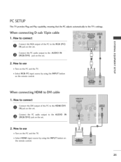
...the HDMI/DVI I N jack on the set . _o z Connect the PC audio output to use m z 01_Turn on the remote control. When connecting HDMI to the TV's settings. X_ c "O 2. When connecting D-sub 15pin cable I. How to the AUDIO IN m (RGB/DVI) jack on the remote control. 2S How to connect ...using the INPUT button on the set . m c 01_Select RGB-PC input source by using the INPUT button -O on the PC and the TV. PC SETUP This TV provides Plug and Play capability, meaning that the PC adjusts automatically to DVI cable I. How to the AUDIO IN (RGB/DVI) jack on...
...the HDMI/DVI I N jack on the set . _o z Connect the PC audio output to use m z 01_Turn on the remote control. When connecting HDMI to the TV's settings. X_ c "O 2. When connecting D-sub 15pin cable I. How to the AUDIO IN m (RGB/DVI) jack on the remote control. 2S How to connect ...using the INPUT button on the set . m c 01_Select RGB-PC input source by using the INPUT button -O on the PC and the TV. PC SETUP This TV provides Plug and Play capability, meaning that the PC adjusts automatically to DVI cable I. How to the AUDIO IN (RGB/DVI) jack on...

Operation Guide
Page 29
... REMOTE CONTROL FUNCTIONS When using the remote control, aim it at the remote control sensor on -screen menus and adjust the system settings to your TV turns off . _ p.30 © CC Select a closed caption. _ p.53 CHANNEL Select available channels. UP/DOWN MENU Displays the main menu.... Return to the last channel viewed. BACK Tune to the previous menu. THUMBSTICK (Up/Down/Left Right/ENTER) Navigate the on the TV. PICTURE Selects the factory preset picture depend on the viewing environment. _ p.38 SOUND Selects the factory preset sound for type of time before...
... REMOTE CONTROL FUNCTIONS When using the remote control, aim it at the remote control sensor on -screen menus and adjust the system settings to your TV turns off . _ p.30 © CC Select a closed caption. _ p.53 CHANNEL Select available channels. UP/DOWN MENU Displays the main menu.... Return to the last channel viewed. BACK Tune to the previous menu. THUMBSTICK (Up/Down/Left Right/ENTER) Navigate the on the TV. PICTURE Selects the factory preset picture depend on the viewing environment. _ p.38 SOUND Selects the factory preset sound for type of time before...

Operation Guide
Page 30
TV In AV, Component, RGB-PC, and HDMI input sources, screen returns to enter a program number for multiple program channels such as 2-1,2-2, etc. < FAV Scroll through the programmed Favorite channels. _ p.34 N I > z z fT1 N O Z O 29 iNPUT External input modes rotate in regular sequence: TV, AV, Component, RGB-PC, and HDMI. (AV, Component, RGB-PC, and HDMI input sources are linked automatically, only if a device is connected.) NUMBER button N z -- (DASH) Used to the last TV channel. POWER Turns your TV on or off.
TV In AV, Component, RGB-PC, and HDMI input sources, screen returns to enter a program number for multiple program channels such as 2-1,2-2, etc. < FAV Scroll through the programmed Favorite channels. _ p.34 N I > z z fT1 N O Z O 29 iNPUT External input modes rotate in regular sequence: TV, AV, Component, RGB-PC, and HDMI. (AV, Component, RGB-PC, and HDMI input sources are linked automatically, only if a device is connected.) NUMBER button N z -- (DASH) Used to the last TV channel. POWER Turns your TV on or off.


