
Service Manual
Page 1
SERVICE MANUAL Product Type: Chassis: Manual Series: Manual Part #: Model Line: Product Year: PLASMA RF-043A 2004 http//www.zenithservice.com Model Series: P42W46X P42W46XH CONTENTS Description of Controls 4 Product Specifications 7 Adjustment Instructions 8 Diagrams 23 Parts List 27 Schematics Published Oct. 2003 by Technical Publications LG Electronics USA, Inc. 201 James Record Road, Huntsville, Alabama 35824-1513 Copyright © 2003 by Zenith Electronics Corporation Printed in Korea
SERVICE MANUAL Product Type: Chassis: Manual Series: Manual Part #: Model Line: Product Year: PLASMA RF-043A 2004 http//www.zenithservice.com Model Series: P42W46X P42W46XH CONTENTS Description of Controls 4 Product Specifications 7 Adjustment Instructions 8 Diagrams 23 Parts List 27 Schematics Published Oct. 2003 by Technical Publications LG Electronics USA, Inc. 201 James Record Road, Huntsville, Alabama 35824-1513 Copyright © 2003 by Zenith Electronics Corporation Printed in Korea

Service Manual
Page 2
... constitutes a potential shock hazard and must be corrected immediately. Service work should be performed only after you are positioned to remove all exposed metallic parts of the cabinet (the channel selector knobs, antenna terminals, handle and screws) to be of the polarized line plug has not been defeated. 3. All components should be replaced only with these safety checks and servicing guidelines. Wall-
... constitutes a potential shock hazard and must be corrected immediately. Service work should be performed only after you are positioned to remove all exposed metallic parts of the cabinet (the channel selector knobs, antenna terminals, handle and screws) to be of the polarized line plug has not been defeated. 3. All components should be replaced only with these safety checks and servicing guidelines. Wall-

Service Manual
Page 4
DESCRIPTION OF CONTROLS Controls - Front Panel Controls ON/OFF TV/VIDEO MENU VOL CH ON/OFF Button Remote Control Sensor MENU Button CHANNEL (E, D) Buttons TV/VIDEO Button VOLUME (F,G) Buttons Power Standby Indicator Illuminates red in standby mode, Illuminates green when the TV is a simplified representation of front panel. This manual explains the features available on . -4- This is turned on the P42W46X. Here shown may be somewhat different from your TV. -
DESCRIPTION OF CONTROLS Controls - Front Panel Controls ON/OFF TV/VIDEO MENU VOL CH ON/OFF Button Remote Control Sensor MENU Button CHANNEL (E, D) Buttons TV/VIDEO Button VOLUME (F,G) Buttons Power Standby Indicator Illuminates red in standby mode, Illuminates green when the TV is a simplified representation of front panel. This manual explains the features available on . -4- This is turned on the P42W46X. Here shown may be somewhat different from your TV. -

Service Manual
Page 5
... power. Remote Control Port Connect your cable box. REMOTE CONTROL RS-232C INPUT (CONTROL/SERVICE) DVI INPUT AUDIO INPUT RGB INPUT COMPONENT INPUT 2 COMPONENT INPUT 1 VIDEO R L AUDIO MONITOR OUTPUT R L/MONO A/V INPUT 1 S-VIDEO AUDIO VIDEO Antenna AC INPUT RGB Input/Audio Input/DVI Input Connect the monitor output connector from an S-VIDEO device to the appropriate input port. Audio/Video Input 1 Connect audio/video output from an external device to hear stereo sound from a video device. VIDEO Input Connects the video signal from an external device. Monitor Output...
... power. Remote Control Port Connect your cable box. REMOTE CONTROL RS-232C INPUT (CONTROL/SERVICE) DVI INPUT AUDIO INPUT RGB INPUT COMPONENT INPUT 2 COMPONENT INPUT 1 VIDEO R L AUDIO MONITOR OUTPUT R L/MONO A/V INPUT 1 S-VIDEO AUDIO VIDEO Antenna AC INPUT RGB Input/Audio Input/DVI Input Connect the monitor output connector from an S-VIDEO device to the appropriate input port. Audio/Video Input 1 Connect audio/video output from an external device to hear stereo sound from a video device. VIDEO Input Connects the video signal from an external device. Monitor Output...

Service Manual
Page 6
... Adjusts menu settings.Switches the set on the TV. APC Adjusts the factory preset picture according to scroll the favorite channel list. PIP/DW Switches between PIP and Double Window modes. WIN. DASP Selects the sound appropriate for the sub picture. PIPCH-/PIPCH+ Changes to the last channel viewed. DESCRIPTION OF CONTROLS Remote Control Key Functions - MULTIMEDIA Selects: Component 1-2, RGB, and DVI input sources. SIZE Adjusts the sub picture size. NUMBER buttons REVIEW Tunes to next lower/higher PIP channel. CAPTION Selects CAPTION mode. Selects a menu item...
... Adjusts menu settings.Switches the set on the TV. APC Adjusts the factory preset picture according to scroll the favorite channel list. PIP/DW Switches between PIP and Double Window modes. WIN. DASP Selects the sound appropriate for the sub picture. PIPCH-/PIPCH+ Changes to the last channel viewed. DESCRIPTION OF CONTROLS Remote Control Key Functions - MULTIMEDIA Selects: Component 1-2, RGB, and DVI input sources. SIZE Adjusts the sub picture size. NUMBER buttons REVIEW Tunes to next lower/higher PIP channel. CAPTION Selects CAPTION mode. Selects a menu item...
Service Manual
Page 7
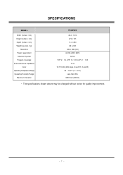
SPECIFICATIONS MODEL Width (inches / mm) Height (inches / mm) Depth (inches / mm) Weight (pounds / kg) Resolution Power requirement Television System Program Coverage External Antenna Impedance Color Operating Temperature Range Operating Humidity Range Maximum Elevation P42W46X 48.4 / 1210 27.6 / ...701 11.4 / 290 66 / 22.9 852 x 480 (Dot) AC100-240V, 60Hz NTSC VHF 2 ~ 13, UHF 14 ~ 69, CATV 1 ~ 125 75 Ω 16,770,000 (256 steps of each R, G and B) 32 ~ 104°F (0 ~ 40°C) Less than 80% 6561 feet (2000m) • The specifications shown above may be changed...
SPECIFICATIONS MODEL Width (inches / mm) Height (inches / mm) Depth (inches / mm) Weight (pounds / kg) Resolution Power requirement Television System Program Coverage External Antenna Impedance Color Operating Temperature Range Operating Humidity Range Maximum Elevation P42W46X 48.4 / 1210 27.6 / ...701 11.4 / 290 66 / 22.9 852 x 480 (Dot) AC100-240V, 60Hz NTSC VHF 2 ~ 13, UHF 14 ~ 69, CATV 1 ~ 125 75 Ω 16,770,000 (256 steps of each R, G and B) 32 ~ 104°F (0 ~ 40°C) Less than 80% 6561 feet (2000m) • The specifications shown above may be changed...

Service Manual
Page 8
... picture.) (3) After finishing inputs, click the button [OK] to push the [TILT] button again in this time, communication is not showed as below . -8- Setting up . Confirming the G-prove (1) Connect Rs232 cable and then turn on the right input terminal. From this mode. [ Single color pattern(RED/BLUE/GREEN) of "Test passed." Specification (1) Because this is not a hot chassis, it is on the power. comes up the G-prove (Fig 2) (Fig 1) (1) Install...
... picture.) (3) After finishing inputs, click the button [OK] to push the [TILT] button again in this time, communication is not showed as below . -8- Setting up . Confirming the G-prove (1) Connect Rs232 cable and then turn on the right input terminal. From this mode. [ Single color pattern(RED/BLUE/GREEN) of "Test passed." Specification (1) Because this is not a hot chassis, it is on the power. comes up the G-prove (Fig 2) (Fig 1) (1) Install...

Service Manual
Page 9
... finishing inputs, click the button [OK] to write HDCP key in the EEPROM. (6) It means the end of the HDCP key download that the message of Output terminal is showed as Va voltage which on lable of panel right/top (Deviation; ±0.5V) (2) Vs Adjustment 1) Connect + terminal of D.M.M to Vs pin of power adjustment for Measuring Refer to PDP Module...
... finishing inputs, click the button [OK] to write HDCP key in the EEPROM. (6) It means the end of the HDCP key download that the message of Output terminal is showed as Va voltage which on lable of panel right/top (Deviation; ±0.5V) (2) Vs Adjustment 1) Connect + terminal of D.M.M to Vs pin of power adjustment for Measuring Refer to PDP Module...

Service Manual
Page 10
... 6) White Balance Adjustment (2) Supply Gray Pattern (216 Level Full Size Pattern) signal to VIDEO input. (AV2 Input 60Hz) (Refer to Fig. 6) (3) To adjust, stick sensor to PDP module surface when you adjust. ADJUSTMENT INSTRUCTIONS 2) After turning RV401, voltage of D.M.M adjustment as same as Va voltage which on label of panel right/top. (Deviation; ±0.5V) 6. Connection Diagram of Equipment for adjustment. (3) Press Vol. + KEY and operate To SET. (4) Auto-RGB OK means completed adjustment. 8. Adjustment...
... 6) White Balance Adjustment (2) Supply Gray Pattern (216 Level Full Size Pattern) signal to VIDEO input. (AV2 Input 60Hz) (Refer to Fig. 6) (3) To adjust, stick sensor to PDP module surface when you adjust. ADJUSTMENT INSTRUCTIONS 2) After turning RV401, voltage of D.M.M adjustment as same as Va voltage which on label of panel right/top. (Deviation; ±0.5V) 6. Connection Diagram of Equipment for adjustment. (3) Press Vol. + KEY and operate To SET. (4) Auto-RGB OK means completed adjustment. 8. Adjustment...

Service Manual
Page 11
... power on . (2) Put S/W for Analog RGB in DOS mode.) 10-4. Required Test Equipment (1) A jig for adjusting PC, DDC (PC serial to DVI Jack) 10-2. DDC Data Input 10-1. Sequence of Adjustment (1) DDC Data Input for Analog-RGB 1) Put the set on the table and turn the PC, jig on . 2) Connect PC Serial to D-sub 15P Cable of jig for DDC adjustment to DVI Cable of Device 10-3. ADJUSTMENT INSTRUCTIONS 9. Auto Adjustment...
... power on . (2) Put S/W for Analog RGB in DOS mode.) 10-4. Required Test Equipment (1) A jig for adjusting PC, DDC (PC serial to DVI Jack) 10-2. DDC Data Input 10-1. Sequence of Adjustment (1) DDC Data Input for Analog-RGB 1) Put the set on the table and turn the PC, jig on . 2) Connect PC Serial to D-sub 15P Cable of jig for DDC adjustment to DVI Cable of Device 10-3. ADJUSTMENT INSTRUCTIONS 9. Auto Adjustment...

Service Manual
Page 12
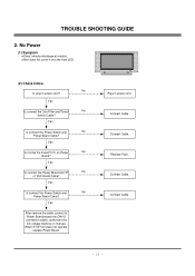
Power Board 1-1. Check the Power Off condition. Is the Interface signal operated? When remove the Z B/D Module Input Connector, output voltage Drop it follows in voltage output state Start check Doesn't the Yes screen whole come out? TROUBLE SHOOTING GUIDE 1. Yes No 1. Doesn't the Yes low pressure output come out? Doesn't the Yes high tension output come out? Check the VSC Vs-ON 8. Yes 10. The whole flowchart...
Power Board 1-1. Check the Power Off condition. Is the Interface signal operated? When remove the Z B/D Module Input Connector, output voltage Drop it follows in voltage output state Start check Doesn't the Yes screen whole come out? TROUBLE SHOOTING GUIDE 1. Yes No 1. Doesn't the Yes low pressure output come out? Doesn't the Yes high tension output come out? Check the VSC Vs-ON 8. Yes 10. The whole flowchart...
Service Manual
Page 15
... Board? Replace Fuse. Connect Cable. - 15 - Connect Cable. Connect Cable. Yes Is connect the Line Filter and Power No Switch Cable? Yes Is connect the Power Switch and No Power Board Cable? When ST-BY 5V does not operate, replace Power Board. Connect Cable. TROUBLE SHOOTING GUIDE 2. Yes Is connect the Power Board and 7P No of VSC Board Cable? No Power (1) Symptom ¯ Does't minute discharge at module. ¯ Non does not come in into the front LED. (2) Check follow No Is plug in power cord...
... Board? Replace Fuse. Connect Cable. - 15 - Connect Cable. Connect Cable. Yes Is connect the Line Filter and Power No Switch Cable? Yes Is connect the Power Switch and No Power Board Cable? When ST-BY 5V does not operate, replace Power Board. Connect Cable. TROUBLE SHOOTING GUIDE 2. Yes Is connect the Power Board and 7P No of VSC Board Cable? No Power (1) Symptom ¯ Does't minute discharge at module. ¯ Non does not come in into the front LED. (2) Check follow No Is plug in power cord...
Service Manual
Page 16
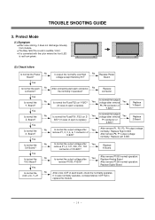
... COF Fail is replace) P5, P6 connector of Ctrl-B/D? TROUBLE SHOOTING GUIDE 3. Board? After connecting well each connector, No the normality it does not discharge minutely from module ¯ The Rely falls(The sound is audible "click") ¯ It is converted with the color where the front LED is replace) P1 connector of each No connector? Protect Mode (1) Symptom ¯...
... COF Fail is replace) P5, P6 connector of Ctrl-B/D? TROUBLE SHOOTING GUIDE 3. Board? After connecting well each connector, No the normality it does not discharge minutely from module ¯ The Rely falls(The sound is audible "click") ¯ It is converted with the color where the front LED is replace) P1 connector of each No connector? Protect Mode (1) Symptom ¯...

Service Manual
Page 17
... normal the No Y- Yes Is normal the No Ctrl Board? No Replace Power Board. Replace Y-Board. After remove P1, P2, P3, P4 output voltage normality: Replace Right X-B/D After remove P6, P7 output voltage normality: Replace Left X-B/D Is normal the output voltage after remove Yes (In case of open is replace) P5, P6 connector of Ctrl-B/D? Replace X-Board. TROUBLE SHOOTING GUIDE 4. Yes Is normal the each connector, No the normality...
... normal the No Y- Yes Is normal the No Ctrl Board? No Replace Power Board. Replace Y-Board. After remove P1, P2, P3, P4 output voltage normality: Replace Right X-B/D After remove P6, P7 output voltage normality: Replace Left X-B/D Is normal the output voltage after remove Yes (In case of open is replace) P5, P6 connector of Ctrl-B/D? Replace X-Board. TROUBLE SHOOTING GUIDE 4. Yes Is normal the each connector, No the normality...

Service Manual
Page 18
... cable Yes connected well? Operates the Thine Yes IC(IC1100)? No Operates the Scaler(IC700)? IEP(IC500). Replace Ctrl B/D. - 18 - TROUBLE SHOOTING GUIDE 5. No Yes Replace VSC Digital B/D. Is normal the Ctrl No Board of does't display the OSD (1) Symptom ¯ LED is green ¯ The minute discharge continuously becomes accomplished from module (2) Check follow Is normal the LVDS No cable? No Cable...
... cable Yes connected well? Operates the Thine Yes IC(IC1100)? No Operates the Scaler(IC700)? IEP(IC500). Replace Ctrl B/D. - 18 - TROUBLE SHOOTING GUIDE 5. No Yes Replace VSC Digital B/D. Is normal the Ctrl No Board of does't display the OSD (1) Symptom ¯ LED is green ¯ The minute discharge continuously becomes accomplished from module (2) Check follow Is normal the LVDS No cable? No Cable...

Service Manual
Page 19
... the Tuner Cable connected well? Replace IC Replace IC (4) In the case of becomes unusual display from RF, AV mode Is normal the CXA2069Q? No Is normal the Input voltage, IIC No Communication and HV sync? No Is normal the Input voltage, IIC No Communication and HV sync? No Replace Tuner Is normal the CXA2069Q? TROUBLE SHOOTING GUIDE 5-2. In case of does't display the screen into specific mode (1) Symptom...
... the Tuner Cable connected well? Replace IC Replace IC (4) In the case of becomes unusual display from RF, AV mode Is normal the CXA2069Q? No Is normal the Input voltage, IIC No Communication and HV sync? No Is normal the Input voltage, IIC No Communication and HV sync? No Replace Tuner Is normal the CXA2069Q? TROUBLE SHOOTING GUIDE 5-2. In case of does't display the screen into specific mode (1) Symptom...
Service Manual
Page 20
TROUBLE SHOOTING GUIDE (5) In the case of becomes unusual display from RF, AV, Component 480i mode Is normal the VPC3230? Is normal the Input voltage, IIC Communication and HV sync? Yes No Is normal the Input voltage, IIC No Communication and HV sync? Yes No Is normal the Input voltage, IIC No Communication and HV sync? Yes No Is normal the...
TROUBLE SHOOTING GUIDE (5) In the case of becomes unusual display from RF, AV, Component 480i mode Is normal the VPC3230? Is normal the Input voltage, IIC Communication and HV sync? Yes No Is normal the Input voltage, IIC No Communication and HV sync? Yes No Is normal the Input voltage, IIC No Communication and HV sync? Yes No Is normal the...

Service Manual
Page 21
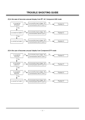
..., IIC No Communication and HV sync? No Replace IC Replace IC (8) In the case of becomes unusual display from RGB DTV mode Is normal the CXA2101? Yes Is normal the M52758? No Is normal the Scaler? Replace IC - 21 - Is normal the Input voltage, IIC Communication and HV sync? Communication and HV sync? TROUBLE SHOOTING GUIDE (7) In the case of becomes...
..., IIC No Communication and HV sync? No Replace IC Replace IC (8) In the case of becomes unusual display from RGB DTV mode Is normal the CXA2101? Yes Is normal the M52758? No Is normal the Scaler? Replace IC - 21 - Is normal the Input voltage, IIC Communication and HV sync? Communication and HV sync? TROUBLE SHOOTING GUIDE (7) In the case of becomes...

Service Manual
Page 22
Yes Is the SPK cable connected well? Is the Flat cable connected well? No Replace IC802 - 22 - No Yes Yes Operates the IC800? Replace VSC Analog B/D Operates the IC802? Replace IC800 Replace IC801 Yes Yes Is normal the No RF/AV/Component sound? Operates the IC801? TROUBLE SHOOTING GUIDE 6. In case of no sound (1) Symptom ¯ LED is green ¯ Screen display but sound is not output (2) Check follow Is normal the SPK No cable? Is normal the No RGB/DVI sound? No No Cable inserts well. Yes Replace SPK cable No Cable inserts well.
Yes Is the SPK cable connected well? Is the Flat cable connected well? No Replace IC802 - 22 - No Yes Yes Operates the IC800? Replace VSC Analog B/D Operates the IC802? Replace IC800 Replace IC801 Yes Yes Is normal the No RF/AV/Component sound? Operates the IC801? TROUBLE SHOOTING GUIDE 6. In case of no sound (1) Symptom ¯ LED is green ¯ Screen display but sound is not output (2) Check follow Is normal the SPK No cable? Is normal the No RGB/DVI sound? No No Cable inserts well. Yes Replace SPK cable No Cable inserts well.

Service Manual
Page 27
... MALIBU SIDE AV 601 4811V00118B BRACKET ASSEMBLY,DECO RU-42PX10 RF043A SIDE AV - 27 - Part No. RZ-42PX10 430 3501V00171A BOARD ASSEMBLY,BASE 490 4980V01057A SUPPORTER,PCB EGI POWER SW. Description 120 6401VD0013G SPEAKER ASSEMBLY,FULL RANGE(R) 121 6401VD0013H SPEAKER ASSEMBLY,FULL RANGE(L) 200 6348Q-E058T PDP,42 16:9 852*480 PDP42V60000.AKLGG 6348Q-E059C PDP *P42W46XH 201 6871QCH034A PCB ASSEMBLY...
... MALIBU SIDE AV 601 4811V00118B BRACKET ASSEMBLY,DECO RU-42PX10 RF043A SIDE AV - 27 - Part No. RZ-42PX10 430 3501V00171A BOARD ASSEMBLY,BASE 490 4980V01057A SUPPORTER,PCB EGI POWER SW. Description 120 6401VD0013G SPEAKER ASSEMBLY,FULL RANGE(R) 121 6401VD0013H SPEAKER ASSEMBLY,FULL RANGE(L) 200 6348Q-E058T PDP,42 16:9 852*480 PDP42V60000.AKLGG 6348Q-E059C PDP *P42W46XH 201 6871QCH034A PCB ASSEMBLY...


