Owner's Manual
Page 2
... safety markings and instructions that is used, please observe all local, state, and federal regulations that contain lead, batteries, plastics, etc. SPECIAL MESSAGE SECTION This product utilizes an external power supply (adapter). DO NOT connect this manual is not recommended! a cart, rack, or stand that accompany the accessory product. SPECIFICATIONS SUBJECT TO CHANGE: The information contained in the manual, on this manual carefully and...
... safety markings and instructions that is used, please observe all local, state, and federal regulations that contain lead, batteries, plastics, etc. SPECIAL MESSAGE SECTION This product utilizes an external power supply (adapter). DO NOT connect this manual is not recommended! a cart, rack, or stand that accompany the accessory product. SPECIFICATIONS SUBJECT TO CHANGE: The information contained in the manual, on this manual carefully and...
Owner's Manual
Page 3
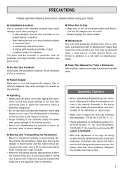
... tone bars could impair the sound. • Rough handling of the controller and/or the driver may impair the performance and functionality of the instrument or cause noise. • Make sure to adjust the wire clip positions after assembly. (YV-3910/3710/3700: P. 17) • Height adjustment of the striking surface (YV3910/3710/3700: P. 18, YV-2700/2700G/ 1600A/520: P 25) should be wiped off using...
... tone bars could impair the sound. • Rough handling of the controller and/or the driver may impair the performance and functionality of the instrument or cause noise. • Make sure to adjust the wire clip positions after assembly. (YV-3910/3710/3700: P. 17) • Height adjustment of the striking surface (YV3910/3710/3700: P. 18, YV-2700/2700G/ 1600A/520: P 25) should be wiped off using...
Owner's Manual
Page 4
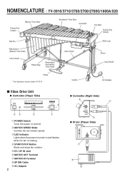
.../3700/2700/2700G/1600A/520 Frame End (Large) Natural Tone Bars Accidental Tone Bars Controller Fan Belt Frame End (Small) Rail No. 1 Resonators (Natural Tone Side) Leg (Large) Pedal Stay Resonators (Accidental Tone Side) Pedal * The illustration shows model YV-3710 Slant Shaft Caster Slide Leg Driver Leg (Small) AC Adapter s Vibes Drive Unit q Controller (Player Side) q Controller (Right Side) q POWER Switch Turns the power on and flashes while...
.../3700/2700/2700G/1600A/520 Frame End (Large) Natural Tone Bars Accidental Tone Bars Controller Fan Belt Frame End (Small) Rail No. 1 Resonators (Natural Tone Side) Leg (Large) Pedal Stay Resonators (Accidental Tone Side) Pedal * The illustration shows model YV-3710 Slant Shaft Caster Slide Leg Driver Leg (Small) AC Adapter s Vibes Drive Unit q Controller (Player Side) q Controller (Right Side) q POWER Switch Turns the power on and flashes while...
Owner's Manual
Page 5
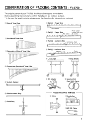
Vibes Drive Unit: YVM-300 !6 Driver !7 Controller !8 8P DIN Cable 3 Before assembling the instrument, confirm that all parts are included as listed. * In the event that a part is missing, please contact the shop where the instrument was purchased. q Natural Tone Bars i Rail (1) : Player Side w Accidental Tone Bars Name Plate o Rail (2) : Player Side Rail Clamp Posts (Larger number than parts !0 and !1) !0 Rail (3) : Audience Side Rail Clamp...
Vibes Drive Unit: YVM-300 !6 Driver !7 Controller !8 8P DIN Cable 3 Before assembling the instrument, confirm that all parts are included as listed. * In the event that a part is missing, please contact the shop where the instrument was purchased. q Natural Tone Bars i Rail (1) : Player Side w Accidental Tone Bars Name Plate o Rail (2) : Player Side Rail Clamp Posts (Larger number than parts !0 and !1) !0 Rail (3) : Audience Side Rail Clamp...
Owner's Manual
Page 6
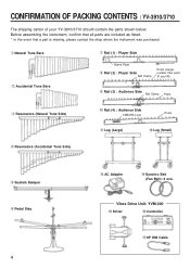
Vibes Drive Unit: YVM-300 !5 Driver !6 Controller !7 8P DIN Cable CONFIRMATION OF PACKING CONTENTS : YV-3910/3710 The shipping carton of your YV-3910/3710 should contain the parts shown below. q Natural Tone Bars w Accidental Tone Bars u Rail (1) : Player Side Name Plate i Rail (2) : Player Side Rail Clamp Posts (Larger number than parts o and !0) o Rail (3) : Audience Side Rail Clamp Posts e Resonators (Natural Tone Side...
Vibes Drive Unit: YVM-300 !5 Driver !6 Controller !7 8P DIN Cable CONFIRMATION OF PACKING CONTENTS : YV-3910/3710 The shipping carton of your YV-3910/3710 should contain the parts shown below. q Natural Tone Bars w Accidental Tone Bars u Rail (1) : Player Side Name Plate i Rail (2) : Player Side Rail Clamp Posts (Larger number than parts o and !0) o Rail (3) : Audience Side Rail Clamp Posts e Resonators (Natural Tone Side...
Owner's Manual
Page 8
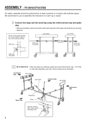
... illustrated. Flat surface should be performed by at least 2 persons in one of the large and small leg are securely fastened. ASSEMBLY : YV-3910/3710/3700 For safety, assembly should face player side. 6 z Connect the large and the small leg using the reinforcement stay and pedal stay. * Before proceeding, make sure that after assembly each slide leg fixing bolt...
... illustrated. Flat surface should be performed by at least 2 persons in one of the large and small leg are securely fastened. ASSEMBLY : YV-3910/3710/3700 For safety, assembly should face player side. 6 z Connect the large and the small leg using the reinforcement stay and pedal stay. * Before proceeding, make sure that after assembly each slide leg fixing bolt...
Owner's Manual
Page 10
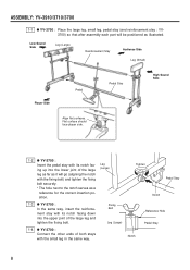
... the large leg and tighten the fixing bolt. 1-4 q YV-3700 : Connect the other ends of both stays with the small leg in the same way. Low Sound Side Leg (Large) Reinforcement Stay Audience Side Leg (Small) Player Side Pedal Pedal Stay High Sound Side Align flat surfaces. ASSEMBLY: YV-3910/3710/3700 1-1 q YV-3700 : Place the large leg, small leg...
... the large leg and tighten the fixing bolt. 1-4 q YV-3700 : Connect the other ends of both stays with the small leg in the same way. Low Sound Side Leg (Large) Reinforcement Stay Audience Side Leg (Small) Player Side Pedal Pedal Stay High Sound Side Align flat surfaces. ASSEMBLY: YV-3910/3710/3700 1-1 q YV-3700 : Place the large leg, small leg...
Owner's Manual
Page 14
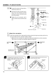
... Fixing Bolt Rod Connector x Turn (screw on) Lock Nut c Secure Center Rod Knurled Part z Loosen Pedal Rod v Attach the resonators. 4-1 Insert the resonators from underneath the frame and rest the high sound side and then the low sound side onto the resonator holders (rubber). * Make sure not to confuse the natural tone side and accidental tone side resonators. * Take...
... Fixing Bolt Rod Connector x Turn (screw on) Lock Nut c Secure Center Rod Knurled Part z Loosen Pedal Rod v Attach the resonators. 4-1 Insert the resonators from underneath the frame and rest the high sound side and then the low sound side onto the resonator holders (rubber). * Make sure not to confuse the natural tone side and accidental tone side resonators. * Take...
Owner's Manual
Page 15
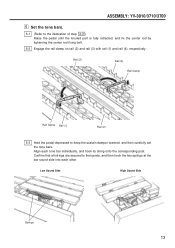
... the pedal until the knurled part is fully retracted, and fix the center rod by tightening the center rod fixing bolt. 5-2 Engage the rail clamp on rail (2) and rail (3) with rail (1) and rail (4), respectively. Align each other. ASSEMBLY: YV-3910/3710/3700 b Set the tone bars. 5-1 (Refer to keep the sustain damper lowered, and then carefully set the tone...
... the pedal until the knurled part is fully retracted, and fix the center rod by tightening the center rod fixing bolt. 5-2 Engage the rail clamp on rail (2) and rail (3) with rail (1) and rail (4), respectively. Align each other. ASSEMBLY: YV-3910/3710/3700 b Set the tone bars. 5-1 (Refer to keep the sustain damper lowered, and then carefully set the tone...
Owner's Manual
Page 17
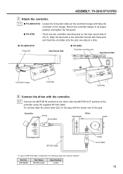
... of the controller using the supplied 8P DIN cable*. To connect align the arrow mark ( ) on the hanger. W5128092 Part Name 8P DIN Cable Specification L=220 Screw Arrow Mark 15 q YV-3910/3710 Fixing bolt High Sound Side q YV-3700 Controller mounting pins High Sound Side Controller hunger Controller Controller , Connect the driver with the controller. 8-1 Connect the MOTOR IN terminal of rail (1). Return the controller hanger to the jack. Controller Screw Arrow...
... of the controller using the supplied 8P DIN cable*. To connect align the arrow mark ( ) on the hanger. W5128092 Part Name 8P DIN Cable Specification L=220 Screw Arrow Mark 15 q YV-3910/3710 Fixing bolt High Sound Side q YV-3700 Controller mounting pins High Sound Side Controller hunger Controller Controller , Connect the driver with the controller. 8-1 Connect the MOTOR IN terminal of rail (1). Return the controller hanger to the jack. Controller Screw Arrow...
Owner's Manual
Page 18
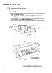
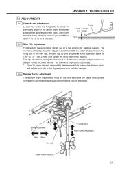
ASSEMBLY: YV-3910/3710/3700 . Tighten the screws securely after adjustment. W5128092 Part Name Synchro Belt Specification 18OTN15-3.0 16 Set the synchro belts (fan belts)*. 9-1 First, wrap the synchro belt around the driver pulley and then carefully slide it over the pulley. * In case the belt is misplaced or worn, the following spare part may be mounted because the...
ASSEMBLY: YV-3910/3710/3700 . Tighten the screws securely after adjustment. W5128092 Part Name Synchro Belt Specification 18OTN15-3.0 16 Set the synchro belts (fan belts)*. 9-1 First, wrap the synchro belt around the driver pulley and then carefully slide it over the pulley. * In case the belt is misplaced or worn, the following spare part may be mounted because the...
Owner's Manual
Page 19
... by turning the spring adjustment wheel counterclockwise. The clip also allows setting the instrument to "half sustain damper" (slight continuous damper effect) or "open damper"* by changing its position accordingly. * To set to "open damper" depress the damper pedal fully to keep the damper open, and set at a low position for packing reasons. Pedal 9/16" ~ 13/16" (1.5 ~ 2 cm) Floor 10-2 Wire Clip Adjustment For shipment the wire clip...
... by turning the spring adjustment wheel counterclockwise. The clip also allows setting the instrument to "half sustain damper" (slight continuous damper effect) or "open damper"* by changing its position accordingly. * To set to "open damper" depress the damper pedal fully to keep the damper open, and set at a low position for packing reasons. Pedal 9/16" ~ 13/16" (1.5 ~ 2 cm) Floor 10-2 Wire Clip Adjustment For shipment the wire clip...
Owner's Manual
Page 20
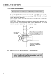
ASSEMBLY: YV-3910/3710/3700 10-4 Tone Bar Height Adjustment This adjustment should always be performed by hand. Loosen the slide leg fixing bolts on the high and low sound sides, while supporting the frame ends by at least 2 persons. Lift the frame ends to the standard height setting. Slide Leg Align notch with the upper leg flange. After assembly, confirm that...
ASSEMBLY: YV-3910/3710/3700 10-4 Tone Bar Height Adjustment This adjustment should always be performed by hand. Loosen the slide leg fixing bolts on the high and low sound sides, while supporting the frame ends by at least 2 persons. Lift the frame ends to the standard height setting. Slide Leg Align notch with the upper leg flange. After assembly, confirm that...
Owner's Manual
Page 21
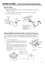
...). BEFORE PLAYING : YV-3910/3710/3700/2700/2700G/1600A/520 s Power Supply Prepare the supplied AC adapter. * Make sure to the DC 12V IN jack on the controller. Use of different adapters may cause damage not covered by sliding it is turned off . z Connect the small plug of the adapter plug. s PAUSE MEMORY FUNCTION SETTING (YV-3910/3710/3700 only) The YV-3910, YV-3710 and YV-3700 are equipped with strongest resonator effect) and...
...). BEFORE PLAYING : YV-3910/3710/3700/2700/2700G/1600A/520 s Power Supply Prepare the supplied AC adapter. * Make sure to the DC 12V IN jack on the controller. Use of different adapters may cause damage not covered by sliding it is turned off . z Connect the small plug of the adapter plug. s PAUSE MEMORY FUNCTION SETTING (YV-3910/3710/3700 only) The YV-3910, YV-3710 and YV-3700 are equipped with strongest resonator effect) and...
Owner's Manual
Page 22
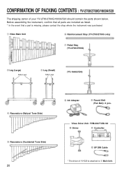
... Legs (YV-1600A/520) r Resonators (Natural Tone Side) t Resonators (Accidental Tone Side) 20 i AC Adapter o Round Belt (Fan Belt): 2 pcs. Before assembling the instrument, confirm that all parts are included as listed. * In the event that a part is attached to q Main Unit. Vibes Drive Unit: YVM-200/YVM-100 !0 Driver !1 Controller !2 8P DIN Cable * The driver of your YV-2700/2700G/1600A/520 should contain the parts shown...
... Legs (YV-1600A/520) r Resonators (Natural Tone Side) t Resonators (Accidental Tone Side) 20 i AC Adapter o Round Belt (Fan Belt): 2 pcs. Before assembling the instrument, confirm that all parts are included as listed. * In the event that a part is attached to q Main Unit. Vibes Drive Unit: YVM-200/YVM-100 !0 Driver !1 Controller !2 8P DIN Cable * The driver of your YV-2700/2700G/1600A/520 should contain the parts shown...
Owner's Manual
Page 24
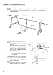
... other ends of the large leg as far as it will be positioned as illustrated. (* YV-1600A/520 is not equipped with a reinforcement stay) Low Sound Side Leg (Large) Reinforcement Stay* Audience Side Pedal Pedal Stay Leg (Small) High Sound Side Player Side 5 Connect the large leg and small leg with the small leg in the same way...
... other ends of the large leg as far as it will be positioned as illustrated. (* YV-1600A/520 is not equipped with a reinforcement stay) Low Sound Side Leg (Large) Reinforcement Stay* Audience Side Pedal Pedal Stay Leg (Small) High Sound Side Player Side 5 Connect the large leg and small leg with the small leg in the same way...
Owner's Manual
Page 25
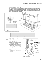
... held securely. 9 After fixing the legs, connect the pedal with the upper leg flange. Do not touch the notched part during height adjustment to extend the center rod. z Loosen Center Rod Fixing Bolt Rod Connector x Turn (screw on) Lock Nut c Secure Center Rod Knurled Part z Loosen Pedal Rod 23 ASSEMBLY : YV-2700/2700G/1600A/520 8 Connect the slide legs with the fitting...
... held securely. 9 After fixing the legs, connect the pedal with the upper leg flange. Do not touch the notched part during height adjustment to extend the center rod. z Loosen Center Rod Fixing Bolt Rod Connector x Turn (screw on) Lock Nut c Secure Center Rod Knurled Part z Loosen Pedal Rod 23 ASSEMBLY : YV-2700/2700G/1600A/520 8 Connect the slide legs with the fitting...
Owner's Manual
Page 26
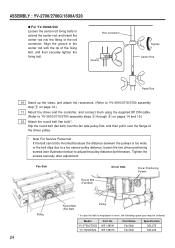
... of the driver pulley. * Note For Service Personnel If the belt cannot be mounted because the distance between the pulleys is misplaced or worn, the following spare part may be ordered: Model YV-2700/2700G YV-1600A/520 Part No. ASSEMBLY : YV-2700/2700G/1600A/520 q For YV-1600A/520 Loosen the...Rod Connector Groove Tighten Center Rod Pedal Rod 10 Stand up the vibes, and attach the resonators. (Refer to YV-3910/3710/3700 assembly step v on page 12.) 11 Mount the driver and the controller, and connect them using the supplied 8P DIN cable. (Refer to adjust the pulley distance (belt tension...
... of the driver pulley. * Note For Service Personnel If the belt cannot be mounted because the distance between the pulleys is misplaced or worn, the following spare part may be ordered: Model YV-2700/2700G YV-1600A/520 Part No. ASSEMBLY : YV-2700/2700G/1600A/520 q For YV-1600A/520 Loosen the...Rod Connector Groove Tighten Center Rod Pedal Rod 10 Stand up the vibes, and attach the resonators. (Refer to YV-3910/3710/3700 assembly step v on page 12.) 11 Mount the driver and the controller, and connect them using the supplied 8P DIN cable. (Refer to adjust the pulley distance (belt tension...
Owner's Manual
Page 27
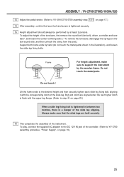
... touch the metal parts shown in between two notches, there is a danger of the slide leg slipping. To play, connect the supplied AC adapter to the DC 12V IN jack of the controller. (Refer to the desired height and then securely tighten each bolt and screw is flush with the corresponding notch of the instrument. ASSEMBLY : YV-2700/2700G/1600A/520 13 Adjust...
... touch the metal parts shown in between two notches, there is a danger of the slide leg slipping. To play, connect the supplied AC adapter to the DC 12V IN jack of the controller. (Refer to the desired height and then securely tighten each bolt and screw is flush with the corresponding notch of the instrument. ASSEMBLY : YV-2700/2700G/1600A/520 13 Adjust...
Owner's Manual
Page 28
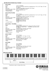
s SPECIFICATIONS/SCALE RANGE q YV-3910 Range Bars Pitch Drive Unit Dimensions (Length x Width) Height Adjustment Oversized Castors c-f3, 3-1/2 Octaves Aluminum Alloy/Glossy Gold Finish, graduating from 1-1/8" to 2-1/5" wide, 1/2" thick A = 442 Hz YVM-300 (Pause-Memory Controller), 25-150 rpm 164 x 79 cm (64-5/8" x 31-1/8") 86-94 cm (33-7/8" x 37") 4" high q YV-3710/YV-3700 Range Bars Pitch Drive Unit Dimensions (Length x Width) Height Adjustment Weight Oversized...
s SPECIFICATIONS/SCALE RANGE q YV-3910 Range Bars Pitch Drive Unit Dimensions (Length x Width) Height Adjustment Oversized Castors c-f3, 3-1/2 Octaves Aluminum Alloy/Glossy Gold Finish, graduating from 1-1/8" to 2-1/5" wide, 1/2" thick A = 442 Hz YVM-300 (Pause-Memory Controller), 25-150 rpm 164 x 79 cm (64-5/8" x 31-1/8") 86-94 cm (33-7/8" x 37") 4" high q YV-3710/YV-3700 Range Bars Pitch Drive Unit Dimensions (Length x Width) Height Adjustment Weight Oversized...

