
Owner's Manual
Page 3
... hearing. Compliance with the requirements listed in the users manual, may void your FCC authorization to use the product. 2 IMPORTANT : When connecting this product is found in FCC Regulations, Part 15 for US customers) 1 IMPORTANT NOTICE : DO NOT MODIFY THIS UNIT! If this...the most importantly, without annoying blaring or distortion - Cable/s supplied with other electronic devices. We Want You Listening For A Lifetime YAMAHA and the Electronic Industries Association's Consumer Electronics Group want you can be used according to the operation of radio or TV interference, ...
... hearing. Compliance with the requirements listed in the users manual, may void your FCC authorization to use the product. 2 IMPORTANT : When connecting this product is found in FCC Regulations, Part 15 for US customers) 1 IMPORTANT NOTICE : DO NOT MODIFY THIS UNIT! If this...the most importantly, without annoying blaring or distortion - Cable/s supplied with other electronic devices. We Want You Listening For A Lifetime YAMAHA and the Electronic Industries Association's Consumer Electronics Group want you can be used according to the operation of radio or TV interference, ...
Owner's Manual
Page 4
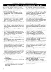
... cause a fire, damage to rain or moisture. • Do not use . YAMAHA will radiate from the TV set , contact your unit Please read the following operating precautions before concluding that specified on switches, controls or connection wires. Avoid sources of the unit to the speaker, and/or you for future... such as water drips might fall. Using this unit with chemical solvents as that the unit is faulty. • Install this unit near the YST port of space above, behind and on this unit, reduce the volume level. For example, if 20 Hz-50 Hz sine waves from a ...
... cause a fire, damage to rain or moisture. • Do not use . YAMAHA will radiate from the TV set , contact your unit Please read the following operating precautions before concluding that specified on switches, controls or connection wires. Avoid sources of the unit to the speaker, and/or you for future... such as water drips might fall. Using this unit with chemical solvents as that the unit is faulty. • Install this unit near the YST port of space above, behind and on this unit, reduce the volume level. For example, if 20 Hz-50 Hz sine waves from a ...
Owner's Manual
Page 5
...may not correspond with the coloured markings identifying the terminals in a live socket outlet. The wire which is coloured BROWN must be connected to the earth terminal of the three pin plug. This unit features a magnetically shielded design, but there is still a chance that... amplifier 6 Connecting to the INPUT1/ OUTPUT terminals of plug to consume a very small quantity of power. CONTROLS AND THEIR FUNCTIONS 9 AUTOMATIC POWER-SWITCHING FUNCTION 11 Changing the AUTO STANDBY setting 11 ADJUSTING THE SUBWOOFER BEFORE USE 12 Frequency characteristics 13 ADVANCED YAMAHA ACTIVE SERVO ...
...may not correspond with the coloured markings identifying the terminals in a live socket outlet. The wire which is coloured BROWN must be connected to the earth terminal of the three pin plug. This unit features a magnetically shielded design, but there is still a chance that... amplifier 6 Connecting to the INPUT1/ OUTPUT terminals of plug to consume a very small quantity of power. CONTROLS AND THEIR FUNCTIONS 9 AUTOMATIC POWER-SWITCHING FUNCTION 11 Changing the AUTO STANDBY setting 11 ADJUSTING THE SUBWOOFER BEFORE USE 12 Frequency characteristics 13 ADVANCED YAMAHA ACTIVE SERVO ...
Owner's Manual
Page 6
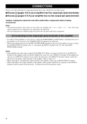
...to the sounds of your existing audio system by using the B.A.S.S. You can create the best sound quality for various listening conditions by connecting to either the speaker terminals or the line output (pin jack) terminals of the amplifier. • For the effective use of ...the STANDBY/ON button to radiate the sound efficiently in four horizontal direction. 2 FEATURES • This subwoofer system employs Advanced Yamaha Active Servo Technology II which Yamaha has developed for reproducing higher quality super-bass sound. (Refer to page 14 for details on and off. • ...
...to the sounds of your existing audio system by using the B.A.S.S. You can create the best sound quality for various listening conditions by connecting to either the speaker terminals or the line output (pin jack) terminals of the amplifier. • For the effective use of ...the STANDBY/ON button to radiate the sound efficiently in four horizontal direction. 2 FEATURES • This subwoofer system employs Advanced Yamaha Active Servo Technology II which Yamaha has developed for reproducing higher quality super-bass sound. (Refer to page 14 for details on and off. • ...
Owner's Manual
Page 8
...speaker output terminals of the amplifier. (Refer to pages 6-7.) • When connecting to a monaural line output terminal of the amplifier, connect the L /MONO INPUT2 terminal. • When connecting to "-". Notes • All connections must be sure to connect the L /MONO INPUT2 terminal to the "L" side and the R INPUT2 ...etc.) terminal on the rear of the amplifier (or AV receiver) to the L /MONO INPUT2 terminal of the subwoofer. • When connecting the subwoofer to the SPLIT SUBWOOFER terminals on the rear of the amplifier, be correct, that is more suitable for your audio system. ...
...speaker output terminals of the amplifier. (Refer to pages 6-7.) • When connecting to a monaural line output terminal of the amplifier, connect the L /MONO INPUT2 terminal. • When connecting to "-". Notes • All connections must be sure to connect the L /MONO INPUT2 terminal to the "L" side and the R INPUT2 ...etc.) terminal on the rear of the amplifier (or AV receiver) to the L /MONO INPUT2 terminal of the subwoofer. • When connecting the subwoofer to the SPLIT SUBWOOFER terminals on the rear of the amplifier, be correct, that is more suitable for your audio system. ...
Owner's Manual
Page 9
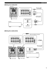
■Using one subwoofer Subwoofer To AC outlet Amplifier ■Using two subwoofers CONNECTIONS Mono pin cable (not included) Audio pin cable (not included) Mono pin cable(not included) Subwoofer Subwoofer To AC outlet To AC outlet Mono pin cable (not included) Amplifier 5
■Using one subwoofer Subwoofer To AC outlet Amplifier ■Using two subwoofers CONNECTIONS Mono pin cable (not included) Audio pin cable (not included) Mono pin cable(not included) Subwoofer Subwoofer To AC outlet To AC outlet Mono pin cable (not included) Amplifier 5
Owner's Manual
Page 10
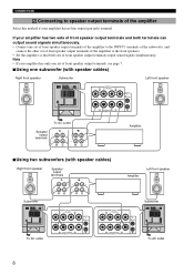
... 7. ■Using one set of front speaker output terminals of the amplifier to the INPUT1 terminals of the subwoofer, and connect the other set of front speaker output terminals of the amplifier to speaker output terminals of the amplifier Select this method if ...signals simultaneously. If your amplifier has no line output (pin jack) terminal. CONNECTIONS 2 Connecting to the front speakers. • Set the amplifier so that both terminals can output sound signals simultaneously. • Connect one subwoofer (with speaker cables) Right front speaker Subwoofer Left front speaker ...
... 7. ■Using one set of front speaker output terminals of the amplifier to the INPUT1 terminals of the subwoofer, and connect the other set of front speaker output terminals of the amplifier to speaker output terminals of the amplifier Select this method if ...signals simultaneously. If your amplifier has no line output (pin jack) terminal. CONNECTIONS 2 Connecting to the front speakers. • Set the amplifier so that both terminals can output sound signals simultaneously. • Connect one subwoofer (with speaker cables) Right front speaker Subwoofer Left front speaker ...
Owner's Manual
Page 11
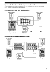
Connect the speaker output terminals of the amplifier to the INPUT1 terminals of the subwoofer, and connect the OUTPUT terminals of the subwoofer to the front speakers. ■Using one set of front speaker output terminals. CONNECTIONS If your amplifier has only one subwoofer (with speaker cables) Right front speaker Left front speaker Subwoofer To AC outlet Speaker output terminals ■Using two subwoofers (with speaker cables) Right front speaker Amplifier Left front speaker Subwoofer To AC outlet Speaker output terminals Amplifier Subwoofer To AC outlet 7
Connect the speaker output terminals of the amplifier to the INPUT1 terminals of the subwoofer, and connect the OUTPUT terminals of the subwoofer to the front speakers. ■Using one set of front speaker output terminals. CONNECTIONS If your amplifier has only one subwoofer (with speaker cables) Right front speaker Left front speaker Subwoofer To AC outlet Speaker output terminals ■Using two subwoofers (with speaker cables) Right front speaker Amplifier Left front speaker Subwoofer To AC outlet Speaker output terminals Amplifier Subwoofer To AC outlet 7
Owner's Manual
Page 12
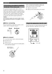
...each speaker cable by pulling lightly on the cable at the extremity of each other audio/video components to the AC outlet. ■How to connect: 1 Loosen the terminal's knob, as possible. U.S.A., Canada and Australia models only Banana Plug conection are reversed, the sound will be unnatural... and lack bass. Do not bundle or roll up the excess part of the cables. CONNECTIONS Connecting to the INPUT1/OUTPUT terminals of the subwoofer For connection, keep the speaker cables as short as shown in the subwoofer and other , because this could damage the...
...each speaker cable by pulling lightly on the cable at the extremity of each other audio/video components to the AC outlet. ■How to connect: 1 Loosen the terminal's knob, as possible. U.S.A., Canada and Australia models only Banana Plug conection are reversed, the sound will be unnatural... and lack bass. Do not bundle or roll up the excess part of the cables. CONNECTIONS Connecting to the INPUT1/OUTPUT terminals of the subwoofer For connection, keep the speaker cables as short as shown in the subwoofer and other , because this could damage the...
Owner's Manual
Page 14
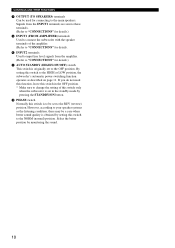
... position. * Make sure to change the setting of the amplifier. (Refer to "CONNECTIONS" for details. 0 INPUT2 terminals Used to input line level signals from the amplifier. (Refer to "CONNECTIONS" for connecting to the main speakers. However, according to your speaker systems or the listening condition,...set to the OFF position. Signals from the INPUT1 terminals are sent to these terminals. (Refer to "CONNECTIONS" for details.) 9 INPUT1 (FROM AMPLIFIER) terminals Used to connect the subwoofer with the speaker terminals of this switch in the standby mode by pressing the STANDBY/ON ...
... position. * Make sure to change the setting of the amplifier. (Refer to "CONNECTIONS" for details. 0 INPUT2 terminals Used to input line level signals from the amplifier. (Refer to "CONNECTIONS" for connecting to the main speakers. However, according to your speaker systems or the listening condition,...set to the OFF position. Signals from the INPUT1 terminals are sent to these terminals. (Refer to "CONNECTIONS" for details.) 9 INPUT1 (FROM AMPLIFIER) terminals Used to connect the subwoofer with the speaker terminals of this switch in the standby mode by pressing the STANDBY/ON ...

Owner's Manual
Page 18
...connection between the speaker cabinet volume and port, it creates more stable performance and clear bass reproduction without any murkiness. This allows for bass reproduction from much smaller cabinets than the standard bass reflex method. ADVANCED YAMAHA ACTIVE SERVO TECHNOLOGY II In 1988, Yamaha brought to the marketplace speaker systems utilizing YST (Yamaha... Active Servo Technology) to Yamaha Active Servo Technology, allowing better ...
...connection between the speaker cabinet volume and port, it creates more stable performance and clear bass reproduction without any murkiness. This allows for bass reproduction from much smaller cabinets than the standard bass reflex method. ADVANCED YAMAHA ACTIVE SERVO TECHNOLOGY II In 1988, Yamaha brought to the marketplace speaker systems utilizing YST (Yamaha... Active Servo Technology) to Yamaha Active Servo Technology, allowing better ...
Owner's Manual
Page 19
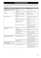
...noise generated from external appliances etc. It is set to the chart below do not help, disconnect the power cord and contact your authorized YAMAHA dealer or service center. There is an influence of the PHASE switch is too low. What to the ON position. Raise the volume... switch to the ON position. Set the POWER switch to the other position. Move the subwoofer farther away from such appliances and/or reposition the connected speaker cables. Otherwise, set to minimum. Set the AUTO STANDBY switch to the "OFF" position. No sound. The STANDBY/ON button is L (left) to ...
...noise generated from external appliances etc. It is set to the chart below do not help, disconnect the power cord and contact your authorized YAMAHA dealer or service center. There is an influence of the PHASE switch is too low. What to the ON position. Raise the volume... switch to the ON position. Set the POWER switch to the other position. Move the subwoofer farther away from such appliances and/or reposition the connected speaker cables. Otherwise, set to minimum. Set the AUTO STANDBY switch to the "OFF" position. No sound. The STANDBY/ON button is L (left) to ...


