
Owner's Manual
Page 1
Please record the serial number of this Owner's Manual in a safe place for future reference. YST-SW500 Active Servo Processing Subwoofer System Built-in 120W Power Amplifier 2 Way Selectability for Connections High Frequency Cut-off Point (HIGH CUT) Control PHASE Switch VOLUME/HIGH CUT/PHASE Adjustment Data Storing Capability 2 Types of Remote Control Signal Code for Controlling 2 Subwoofers Thank you to the presence of uninsulated "dangerous voltage" within the product's enclosure that...
Please record the serial number of this Owner's Manual in a safe place for future reference. YST-SW500 Active Servo Processing Subwoofer System Built-in 120W Power Amplifier 2 Way Selectability for Connections High Frequency Cut-off Point (HIGH CUT) Control PHASE Switch VOLUME/HIGH CUT/PHASE Adjustment Data Storing Capability 2 Types of Remote Control Signal Code for Controlling 2 Subwoofers Thank you to the presence of uninsulated "dangerous voltage" within the product's enclosure that...
Owner's Manual
Page 2
... Hz - 50 Hz sine waves from a test disc, bass sounds from windows, heat sources, sources of the type described in performance; The safety and operating instructions should not be referred to prevent this unit away from the TV set. 12 This unit may impede the flow of time (ie., vacation, etc.), disconnect the AC power plug from the unit. 12 Cleaning - The unit...
... Hz - 50 Hz sine waves from a test disc, bass sounds from windows, heat sources, sources of the type described in performance; The safety and operating instructions should not be referred to prevent this unit away from the TV set. 12 This unit may impede the flow of time (ie., vacation, etc.), disconnect the AC power plug from the unit. 12 Cleaning - The unit...
Owner's Manual
Page 3
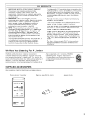
..., UM-3) Speaker Cords POWER CODE I2 ON/OFF NOM/REV OUTPUT PHASE PRESET MEMORY 2 3 UP UP DOWN DOWN HIGH-CUT VOLUME Active Servo Technology REMOTE CONTROL TRANSMITTER 3 This equipment generates/uses radio frequencies and, if not installed and used . FCC INFORMATION 1. IMPORTANT : When connecting this manual, meets FCC requirements. Failure to follow instructions could void your authority, granted by the FCC, to eliminate the problem by Yamaha Corporation of...
..., UM-3) Speaker Cords POWER CODE I2 ON/OFF NOM/REV OUTPUT PHASE PRESET MEMORY 2 3 UP UP DOWN DOWN HIGH-CUT VOLUME Active Servo Technology REMOTE CONTROL TRANSMITTER 3 This equipment generates/uses radio frequencies and, if not installed and used . FCC INFORMATION 1. IMPORTANT : When connecting this manual, meets FCC requirements. Failure to follow instructions could void your authority, granted by the FCC, to eliminate the problem by Yamaha Corporation of...
Owner's Manual
Page 4
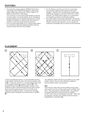
...; As a utility function for using two subwoofers, this unit's super-bass sound must be a case that you can be necessary to break up the parallel surfaces by connecting to either the right or the left main speaker. (See fig. To prevent this unit employs the continuously variable high frequency cut-off point (HIGH-CUT) control. A .) If using one remote control transmitter. Therefore...
...; As a utility function for using two subwoofers, this unit's super-bass sound must be a case that you can be necessary to break up the parallel surfaces by connecting to either the right or the left main speaker. (See fig. To prevent this unit employs the continuously variable high frequency cut-off point (HIGH-CUT) control. A .) If using one remote control transmitter. Therefore...
Owner's Manual
Page 5
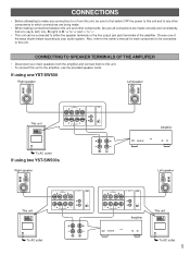
... speaker cords. If using two YST-SW500s Right speaker R L Amplifier Left speaker This unit OUTPUT TO SPEAKERS +R L+ INPUT2 REMOTE CODE L R +R L+ FROM AMPLIFIER INPUT1 12 To AC outlet OUTPUT TO SPEAKERS +R L+ INPUT2 REMOTE CODE L R +R L+ FROM AMPLIFIER INPUT1 12 + + R L OUTPUT TO SPEAKERS +R L+ INPUT2 REMOTE CODE L R +R L+ FROM AMPLIFIER INPUT1 12 Amplifier This unit OUTPUT TO SPEAKERS +R L+ INPUT2 REMOTE CODE L R +R L+ FROM AMPLIFIER INPUT1 12 To AC outlet 5 Also, refer to the owner's manual for each component to be connected...
... speaker cords. If using two YST-SW500s Right speaker R L Amplifier Left speaker This unit OUTPUT TO SPEAKERS +R L+ INPUT2 REMOTE CODE L R +R L+ FROM AMPLIFIER INPUT1 12 To AC outlet OUTPUT TO SPEAKERS +R L+ INPUT2 REMOTE CODE L R +R L+ FROM AMPLIFIER INPUT1 12 + + R L OUTPUT TO SPEAKERS +R L+ INPUT2 REMOTE CODE L R +R L+ FROM AMPLIFIER INPUT1 12 Amplifier This unit OUTPUT TO SPEAKERS +R L+ INPUT2 REMOTE CODE L R +R L+ FROM AMPLIFIER INPUT1 12 To AC outlet 5 Also, refer to the owner's manual for each component to be connected...
Owner's Manual
Page 6
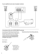
... REMOTE CODE L R +R L+ FROM AMPLIFIER INPUT1 12 OUTPUT TO SPEAKERS +R L+ INPUT2 REMOTE CODE L R +R L+ FROM AMPLIFIER INPUT1 12 Left speaker To AC outlet A + + B + + R L R L Amplifier (Both "A" and "B" outputs must be ON.) Connecting to Connect: Red: positive (+) Black: negative (-) 2 1 3 ΠUnscrew the knob. Insert the bare wire. [Remove approx. 5mm (1/4") insulation from the speakers. If the connections are also possible. If your amplifier and/or speakers. * Banana Plug connections are faulty, no sound will lack bass...
... REMOTE CODE L R +R L+ FROM AMPLIFIER INPUT1 12 OUTPUT TO SPEAKERS +R L+ INPUT2 REMOTE CODE L R +R L+ FROM AMPLIFIER INPUT1 12 Left speaker To AC outlet A + + B + + R L R L Amplifier (Both "A" and "B" outputs must be ON.) Connecting to Connect: Red: positive (+) Black: negative (-) 2 1 3 ΠUnscrew the knob. Insert the bare wire. [Remove approx. 5mm (1/4") insulation from the speakers. If the connections are also possible. If your amplifier and/or speakers. * Banana Plug connections are faulty, no sound will lack bass...
Owner's Manual
Page 7
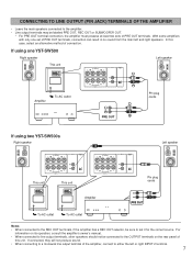
... INPUT 2 terminal. 7 With some amplifiers with only one YST-SW500 Right speaker Left speaker This unit OUTPUT TO SPEAKERS +R L+ INPUT2 REMOTE CODE L R +R L+ FROM AMPLIFIER INPUT1 12 OUTPUT TO SPEAKERS +R L+ INPUT2 REMOTE CODE L R +R L+ FROM AMPLIFIER INPUT1 12 Amplifier To AC outlet Pin plug cords PRE OUT If using one set of the amplifier, connect to set it for the correct source. For information on the rear panel of this case, select an alternative method of PRE OUT terminals. If using two YST-SW500s Right speaker...
... INPUT 2 terminal. 7 With some amplifiers with only one YST-SW500 Right speaker Left speaker This unit OUTPUT TO SPEAKERS +R L+ INPUT2 REMOTE CODE L R +R L+ FROM AMPLIFIER INPUT1 12 OUTPUT TO SPEAKERS +R L+ INPUT2 REMOTE CODE L R +R L+ FROM AMPLIFIER INPUT1 12 Amplifier To AC outlet Pin plug cords PRE OUT If using one set of the amplifier, connect to set it for the correct source. For information on the rear panel of this case, select an alternative method of PRE OUT terminals. If using two YST-SW500s Right speaker...

Owner's Manual
Page 8
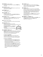
...panel 1PRE2SET3 PHASEOUTPUT POWER HIGH40CHUzT I40VHOzLUM0E I0 1PR1E2S,,,,,,ET3 P5H,,,,,,ASE O,,,,,,U2TPUT,,,,,,6 ,,,,,,PO3WER,,,,,,,,,,,,HIGH4,,,,,,0CHUzT7,,,,,,I40VHOz,,,,,,LUM0E4,,,,,,I0 ,,,,,, Rear panel OUTPUT TO SPEAKERS +R L+ INPUT2 REMOTE CODE L R +R L+ FROM AMPLIFIER INPUT1 12 OUTPUT TO SPEAKERS +R L+ INPUT2 REMOTE CODE L R +R L+ FROM AMPLIFIER INPUT1 12 8 Remote control transmitter I2 POWER CODE 3 8 9 ON/OFF NOM/REV OUTPUT PHASE PRESET MEMORY 2 3 0 A 7 UP UP DOWN DOWN HIGH-CUT VOLUME 4 8 Active Servo Technology REMOTE CONTROL...
...panel 1PRE2SET3 PHASEOUTPUT POWER HIGH40CHUzT I40VHOzLUM0E I0 1PR1E2S,,,,,,ET3 P5H,,,,,,ASE O,,,,,,U2TPUT,,,,,,6 ,,,,,,PO3WER,,,,,,,,,,,,HIGH4,,,,,,0CHUzT7,,,,,,I40VHOz,,,,,,LUM0E4,,,,,,I0 ,,,,,, Rear panel OUTPUT TO SPEAKERS +R L+ INPUT2 REMOTE CODE L R +R L+ FROM AMPLIFIER INPUT1 12 OUTPUT TO SPEAKERS +R L+ INPUT2 REMOTE CODE L R +R L+ FROM AMPLIFIER INPUT1 12 8 Remote control transmitter I2 POWER CODE 3 8 9 ON/OFF NOM/REV OUTPUT PHASE PRESET MEMORY 2 3 0 A 7 UP UP DOWN DOWN HIGH-CUT VOLUME 4 8 Active Servo Technology REMOTE CONTROL...
Owner's Manual
Page 9
... remote control transmitter. 9 OUTPUT switch Turns the output of this unit ON and OFF whenever pressed. A MEMORY key/PRESET keys Used to store and recall the data for remote control. If using one YST-SW500; When you will control two units at the same time with the remote control transmitter, set the CODE switches on the rear panel of this control indicates 50 10 Hz.130 40 Hz 140 Hz 8 (REMOTE) CODE switch Switches the signal codes for the VOLUME control...
... remote control transmitter. 9 OUTPUT switch Turns the output of this unit ON and OFF whenever pressed. A MEMORY key/PRESET keys Used to store and recall the data for remote control. If using one YST-SW500; When you will control two units at the same time with the remote control transmitter, set the CODE switches on the rear panel of this control indicates 50 10 Hz.130 40 Hz 140 Hz 8 (REMOTE) CODE switch Switches the signal codes for the VOLUME control...
Owner's Manual
Page 10
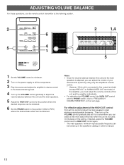
... power supply to all the components. 3 Play the source and adjust the amplifier's volume control to the desired listening level. 4 Turn up the VOLUME control gradually to minimum. 2 Turn on the next page. On the basis of this setting, if desired, adjust the VOLUME control and the HIGH CUT control again. * The main speakers' minimum reproduceable frequency can be obtained. Then turn up in the speakers' catalog or owner's manual. 10 ADJUSTING VOLUME BALANCE For these operations, use the remote control...
... power supply to all the components. 3 Play the source and adjust the amplifier's volume control to the desired listening level. 4 Turn up the VOLUME control gradually to minimum. 2 Turn on the next page. On the basis of this setting, if desired, adjust the VOLUME control and the HIGH CUT control again. * The main speakers' minimum reproduceable frequency can be obtained. Then turn up in the speakers' catalog or owner's manual. 10 ADJUSTING VOLUME BALANCE For these operations, use the remote control...
Owner's Manual
Page 11
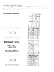
... PHASE-Reverse (The PHASE indicator on the front panel illuminates in green.) • When combined with a typical speaker system. The following figures show the optimum adjusting level of the VOLUME control, the HIGH CUT control and the PHASE switch should be changed according to the main speakers, listening condition, the source, etc. This unit's frequency characteristics • When combined with a 4" or 5" acoustic...
... PHASE-Reverse (The PHASE indicator on the front panel illuminates in green.) • When combined with a typical speaker system. The following figures show the optimum adjusting level of the VOLUME control, the HIGH CUT control and the PHASE switch should be changed according to the main speakers, listening condition, the source, etc. This unit's frequency characteristics • When combined with a 4" or 5" acoustic...
Owner's Manual
Page 12
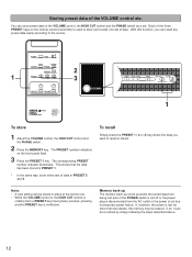
... PHASE switch as a set. If, however, the power is lost even if the POWER switch is cut due to the source. 1 POWER CODE I2 ON/OFF NOM/REV OUTPUT PHASE PRESET MEMORY 2 3 UP UP DOWN DOWN HIGH-CUT VOLUME Active Servo Technology REMOTE CONTROL TRANSMITTER 2 3 1PRE2SET3 PHASEOUTPUT POWER HIGH40CHUzT I40VHOzLUM0E I0 1PRE2S,,,,,,ET3 PH,,,,,,ASE O,,,,,,UTPUT,,,,,,,,,,,,POWER,,,,,,,,,,,,HIGH4,,,,,,0CHUzT ,,,,,,I40VHOz,,,,,,LUM0E ,,,,,,I0 ,,,,,, 1 To store 1 Adjust the VOLUME control...
... PHASE switch as a set. If, however, the power is lost even if the POWER switch is cut due to the source. 1 POWER CODE I2 ON/OFF NOM/REV OUTPUT PHASE PRESET MEMORY 2 3 UP UP DOWN DOWN HIGH-CUT VOLUME Active Servo Technology REMOTE CONTROL TRANSMITTER 2 3 1PRE2SET3 PHASEOUTPUT POWER HIGH40CHUzT I40VHOzLUM0E I0 1PRE2S,,,,,,ET3 PH,,,,,,ASE O,,,,,,UTPUT,,,,,,,,,,,,POWER,,,,,,,,,,,,HIGH4,,,,,,0CHUzT ,,,,,,I40VHOz,,,,,,LUM0E ,,,,,,I0 ,,,,,, 1 To store 1 Adjust the VOLUME control...
Owner's Manual
Page 13
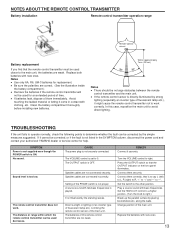
... the parallel surface by the standing waves. Replace both batteries with new ones. 13 SYMPTOM Power is not supplied even though the POWER switch is not securely connected. Speaker cables are too weak. It is played. Set the HIGH-CUT control to a higher position. (Turn the knob to avoid direct lighting. A source sound with bass frequencies. along the walls. Notes q Use only AA, R6, UM-3 batteries for an...
... the parallel surface by the standing waves. Replace both batteries with new ones. 13 SYMPTOM Power is not supplied even though the POWER switch is not securely connected. Speaker cables are too weak. It is played. Set the HIGH-CUT control to a higher position. (Turn the knob to avoid direct lighting. A source sound with bass frequencies. along the walls. Notes q Use only AA, R6, UM-3 batteries for an...
Owner's Manual
Page 14
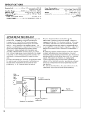
... a conventionally designed speaker system. SPECIFICATIONS Speaker Unit 25 cm (10") cone woofer (JA2540) magnetic-shield type Amplifier Output 120W/5 ohms (THD 0.1%, 100 Hz) High-Cut Filter 40 Hz-140 Hz (-24 dB/oct.) Frequency Response 20 Hz-160 Hz (-10 dB) Power Supply U.S.A. Thus, signals of the Active Servo Technology. The system can , according to generate precise, low-amplitude low-frequency waves with...
... a conventionally designed speaker system. SPECIFICATIONS Speaker Unit 25 cm (10") cone woofer (JA2540) magnetic-shield type Amplifier Output 120W/5 ohms (THD 0.1%, 100 Hz) High-Cut Filter 40 Hz-140 Hz (-24 dB/oct.) Frequency Response 20 Hz-160 Hz (-10 dB) Power Supply U.S.A. Thus, signals of the Active Servo Technology. The system can , according to generate precise, low-amplitude low-frequency waves with...

Owner's Manual
Page 15
... 30053, 400 43 VÄSTRA FRÖLUNDA, SWEDEN YAMAHA MUSIC AUSTRALIA PTY, LTD. 17-33 MARKET ST., SOUTH MELBOURNE, 3205 VIC., AUSTRALIA VP16310-0 BWWB,W Printed in Japan OF GERMANY YAMAHA ELECTRONIQUE FRANCE S.A. YAMAHA HOUSE, 200 RICKMANSWORTH ROAD WATFORD, HERTS WD1 7JS, ENGLAND YAMAHA SCANDINAVIA A.B. YAMAHA CANADA MUSIC LTD. 135 MILNER AVE., SCARBOROUGH, ONTARIO M1S 3R1, CANADA...
... 30053, 400 43 VÄSTRA FRÖLUNDA, SWEDEN YAMAHA MUSIC AUSTRALIA PTY, LTD. 17-33 MARKET ST., SOUTH MELBOURNE, 3205 VIC., AUSTRALIA VP16310-0 BWWB,W Printed in Japan OF GERMANY YAMAHA ELECTRONIQUE FRANCE S.A. YAMAHA HOUSE, 200 RICKMANSWORTH ROAD WATFORD, HERTS WD1 7JS, ENGLAND YAMAHA SCANDINAVIA A.B. YAMAHA CANADA MUSIC LTD. 135 MILNER AVE., SCARBOROUGH, ONTARIO M1S 3R1, CANADA...


