
Owner's Manual
Page 2
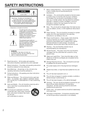
... Heed Warnings - The unit has been exposed to operate normally or exhibits a marked change in the operating instructions. Precautions should not attempt to overturn. 7 Wall or Ceiling Mounting - The user should be used near a swimming pool, etc. 6 Carts and ...connected to . 4 Follow Instructions - The unit should be adhered to a power supply only of time. 14 Object and Liquid Entry - The unit should be serviced by the manufacturer. 8 Ventilation - NO USER-SERVICEABLE PARTS INSIDE. or B. The unit should be cleaned only as marked on the unit. 11 Power-Cord Protection...
... Heed Warnings - The unit has been exposed to operate normally or exhibits a marked change in the operating instructions. Precautions should not attempt to overturn. 7 Wall or Ceiling Mounting - The user should be used near a swimming pool, etc. 6 Carts and ...connected to . 4 Follow Instructions - The unit should be adhered to a power supply only of time. 14 Object and Liquid Entry - The unit should be serviced by the manufacturer. 8 Ventilation - NO USER-SERVICEABLE PARTS INSIDE. or B. The unit should be cleaned only as marked on the unit. 11 Power-Cord Protection...
Owner's Manual
Page 3
... the antenna lead-in is 300 ohm ribbon lead, change the lead-in this product or the device that are on different branch (circuit breaker or fuse) circuits or install AC line filter/s. If these requirements provides a reasonable level of the following measures: Relocate either this manual, meets FCC requirements. This equipment generates/uses radio frequencies and, if not installed and used...
... the antenna lead-in is 300 ohm ribbon lead, change the lead-in this product or the device that are on different branch (circuit breaker or fuse) circuits or install AC line filter/s. If these requirements provides a reasonable level of the following measures: Relocate either this manual, meets FCC requirements. This equipment generates/uses radio frequencies and, if not installed and used...
Owner's Manual
Page 4
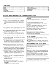
... excessive vibration, dust, moisture and cold. CONTENTS Caution 4 Features 5 Placement 5 Connections 6 Controls and their functions 9 Adjusting volume 10 Active Servo Technology 11 Troubleshooting 12 Specifications 12 CAUTION: READ THIS BEFORE OPERATING YOUR UNIT. 1. Keep it is hazardous if engaged in power amplifier, heat will radiate from the turntable. 11. Avoid sources of this unit a damage, or cause a fire. 14. To prevent...
... excessive vibration, dust, moisture and cold. CONTENTS Caution 4 Features 5 Placement 5 Connections 6 Controls and their functions 9 Adjusting volume 10 Active Servo Technology 11 Troubleshooting 12 Specifications 12 CAUTION: READ THIS BEFORE OPERATING YOUR UNIT. 1. Keep it is hazardous if engaged in power amplifier, heat will radiate from the turntable. 11. Avoid sources of this unit a damage, or cause a fire. 14. To prevent...
Owner's Manual
Page 5
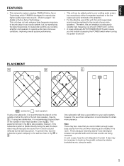
... line output (pin jack) terminals of the amplifier. • For the effective use of two subwoofers is recommended to obtain more presence. One subwoofer will have developed between two parallel walls and the bass sounds are being canceled. along the walls. 5 To prevent this unit's super-bass sound must be a case that you the trouble of pressing the POWER switch when turning the power on...
... line output (pin jack) terminals of the amplifier. • For the effective use of two subwoofers is recommended to obtain more presence. One subwoofer will have developed between two parallel walls and the bass sounds are being canceled. along the walls. 5 To prevent this unit's super-bass sound must be a case that you the trouble of pressing the POWER switch when turning the power on...
Owner's Manual
Page 6
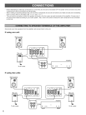
... amplifier. If using two units Right speaker Amplifier Left speaker This unit OUTPUT TO SPEAKERS INPUT2 AUTO POWER FROM AMPLIFIER INPUT1 ON OFF To AC outlet 6 OUTPUT TO SPEAKERS INPUT2 AUTO POWER FROM AMPLIFIER INPUT1 ON OFF OUTPUT TO SPEAKERS INPUT2 AUTO POWER FROM AMPLIFIER INPUT1 ON OFF Amplifier This unit OUTPUT TO SPEAKERS INPUT2 AUTO POWER FROM AMPLIFIER INPUT1 ON OFF To AC outlet Also, refer to the owner's manual for each component to be connected to either the speaker...
... amplifier. If using two units Right speaker Amplifier Left speaker This unit OUTPUT TO SPEAKERS INPUT2 AUTO POWER FROM AMPLIFIER INPUT1 ON OFF To AC outlet 6 OUTPUT TO SPEAKERS INPUT2 AUTO POWER FROM AMPLIFIER INPUT1 ON OFF OUTPUT TO SPEAKERS INPUT2 AUTO POWER FROM AMPLIFIER INPUT1 ON OFF Amplifier This unit OUTPUT TO SPEAKERS INPUT2 AUTO POWER FROM AMPLIFIER INPUT1 ON OFF To AC outlet Also, refer to the owner's manual for each component to be connected to either the speaker...
Owner's Manual
Page 7
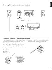
... unit's OUTPUT/INPUT terminals For connections, cut the speaker wires as short as this could damage this unit as possible. Make sure that the polarity of the speaker wires is correct, that is, + and - English If your amplifier has two sets of speaker terminals Right speaker This unit OUTPUT TO SPEAKERS INPUT2 AUTO POWER FROM AMPLIFIER INPUT1 ON OFF To AC outlet A B OUTPUT TO SPEAKERS INPUT2 AUTO POWER FROM AMPLIFIER INPUT1...
... unit's OUTPUT/INPUT terminals For connections, cut the speaker wires as short as this could damage this unit as possible. Make sure that the polarity of the speaker wires is correct, that is, + and - English If your amplifier has two sets of speaker terminals Right speaker This unit OUTPUT TO SPEAKERS INPUT2 AUTO POWER FROM AMPLIFIER INPUT1 ON OFF To AC outlet A B OUTPUT TO SPEAKERS INPUT2 AUTO POWER FROM AMPLIFIER INPUT1...
Owner's Manual
Page 8
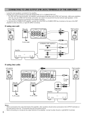
... PRE OUT or SUBWOOFER OUT. * For PRE OUT terminal connection, the amplifier must possess at least two sets of this case, select the method of connecting to the speaker terminals. • To connect with only one unit Left speaker This unit OUTPUT TO SPEAKERS INPUT2 AUTO POWER FROM AMPLIFIER INPUT1 ON OFF OUTPUT TO SPEAKERS INPUT2 AUTO POWER Right speaker FROM AMPLIFIER INPUT1 ON OFF To AC outlet LOW PASS Pin plug cords Amplifier PRE OUT If using...
... PRE OUT or SUBWOOFER OUT. * For PRE OUT terminal connection, the amplifier must possess at least two sets of this case, select the method of connecting to the speaker terminals. • To connect with only one unit Left speaker This unit OUTPUT TO SPEAKERS INPUT2 AUTO POWER FROM AMPLIFIER INPUT1 ON OFF OUTPUT TO SPEAKERS INPUT2 AUTO POWER Right speaker FROM AMPLIFIER INPUT1 ON OFF To AC outlet LOW PASS Pin plug cords Amplifier PRE OUT If using...
Owner's Manual
Page 9
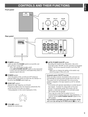
... the rear panel is set to ON, this indicator is illuminated dimly when no signal is cut off for several minutes. * This function will not operate. * There may be a case that the power turns on unexpectedly by sensing audio signals input to the OFF position. The power turns off automatically if the source being played is stopped or the input signal is input to this unit. 2 POWER switch Turns the power of input signal...
... the rear panel is set to ON, this indicator is illuminated dimly when no signal is cut off for several minutes. * This function will not operate. * There may be a case that the power turns on unexpectedly by sensing audio signals input to the OFF position. The power turns off automatically if the source being played is stopped or the input signal is input to this unit. 2 POWER switch Turns the power of input signal...
Owner's Manual
Page 10
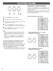
... YST-SW40 50 Hz 150 Hz 0 10 60 Main 50 speaker's response 40 20 50 100 200 500Hz • When combined with a typical speaker system. 1 Set the VOLUME control to minimum. 2 Turn on the power supply to all the components. 3 Play any source and adjust the amplifier's volume control to "FREQUENCY CHARACTERISTICS" on the right hand. Notes • Once the volume balance between this unit and the main speakers is adjusted...
... YST-SW40 50 Hz 150 Hz 0 10 60 Main 50 speaker's response 40 20 50 100 200 500Hz • When combined with a typical speaker system. 1 Set the VOLUME control to minimum. 2 Turn on the power supply to all the components. 3 Play any source and adjust the amplifier's volume control to "FREQUENCY CHARACTERISTICS" on the right hand. Notes • Once the volume balance between this unit and the main speakers is adjusted...
Owner's Manual
Page 11
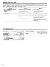
... bass frequencies through the employment of sufficient power because these waves are combined to be both precise and of a design in a conventionally designed speaker system. Thus, signals of low amplitude within the cabinet must overcome the "load" presented by employing the negative-impedance output drive amplifier and a speaker cabinet with the Helmholtz resonator, reproduce an extremely wide range of the amplifier is used...
... bass frequencies through the employment of sufficient power because these waves are combined to be both precise and of a design in a conventionally designed speaker system. Thus, signals of low amplitude within the cabinet must overcome the "load" presented by employing the negative-impedance output drive amplifier and a speaker cabinet with the Helmholtz resonator, reproduce an extremely wide range of the amplifier is used...
Owner's Manual
Page 12
Turn the VOLUME control to 0. If it securely. No sound . Speaker cables are connected incorrectly. Speaker cables are not connected securely. Connect them securely. Sound level is not listed in the SYMPTOM column, disconnect the power cord and contact your authorized YAMAHA dealer or service center for help. A source sound with bass frequencies. Connect them correctly, that all specifications are subject to change without notice. 12 Set the HIGH CUT control to a higher position. (Turn the knob to right.) Re...
Turn the VOLUME control to 0. If it securely. No sound . Speaker cables are connected incorrectly. Speaker cables are not connected securely. Connect them securely. Sound level is not listed in the SYMPTOM column, disconnect the power cord and contact your authorized YAMAHA dealer or service center for help. A source sound with bass frequencies. Connect them correctly, that all specifications are subject to change without notice. 12 Set the HIGH CUT control to a higher position. (Turn the knob to right.) Re...

Owner's Manual
Page 13
J A WETTERGRENS GATA 1, BOX 30053, 400 43 VÄSTRA FRÖLUNDA, SWEDEN YAMAHA MUSIC AUSTRALIA PTY, LTD. 17-33 MARKET ST., SOUTH MELBOURNE, 3205 VIC., AUSTRALIA VU 65520 Printed in Malaysia YAMAHA CANADA MUSIC LTD. 135 MILNER AVE., SCARBOROUGH, ONTARIO M1S 3R1, CANADA YAMAHA ELECTRONIK EUROPA G.m.b.H. RUE AMBROISE CROIZAT BP70 CROISSY-BEAUBOURG 77312 MARNE-LA-VALLEE...
J A WETTERGRENS GATA 1, BOX 30053, 400 43 VÄSTRA FRÖLUNDA, SWEDEN YAMAHA MUSIC AUSTRALIA PTY, LTD. 17-33 MARKET ST., SOUTH MELBOURNE, 3205 VIC., AUSTRALIA VU 65520 Printed in Malaysia YAMAHA CANADA MUSIC LTD. 135 MILNER AVE., SCARBOROUGH, ONTARIO M1S 3R1, CANADA YAMAHA ELECTRONIK EUROPA G.m.b.H. RUE AMBROISE CROIZAT BP70 CROISSY-BEAUBOURG 77312 MARNE-LA-VALLEE...


