
Owner's Manual
Page 2
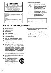
... persons. A polarized plug has two blades with dry cloth. 7 Do not block any ventilation openings. The wide blade or the third prong are provided for your outlet, consult an electrician for replacement of the obsolete outlet. 10 Protect the power cord from being walked on the rear of time. 14 Refer all instructions. 5 Do not use caution when moving...
... persons. A polarized plug has two blades with dry cloth. 7 Do not block any ventilation openings. The wide blade or the third prong are provided for your outlet, consult an electrician for replacement of the obsolete outlet. 10 Protect the power cord from being walked on the rear of time. 14 Refer all instructions. 5 Do not use caution when moving...
Owner's Manual
Page 3
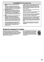
..., Buena Park, CA 90620. FCC INFORMATION (for Class "B" digital devices. IMPORTANT NOTICE : DO NOT MODIFY THIS UNIT! Follow all installations. NOTE : This product has been tested and found in the USA. 3. If the antenna lead-in is found to those products distributed by playing it at a safe level. This equipment generates/uses radio frequencies and, if not installed and used . III
..., Buena Park, CA 90620. FCC INFORMATION (for Class "B" digital devices. IMPORTANT NOTICE : DO NOT MODIFY THIS UNIT! Follow all installations. NOTE : This product has been tested and found in the USA. 3. If the antenna lead-in is found to those products distributed by playing it at a safe level. This equipment generates/uses radio frequencies and, if not installed and used . III
Owner's Manual
Page 5
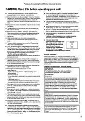
... selector switch on the front panel, this unit consumes a small amount of a disc, reduce the volume level to generate a howling sound. MODEL IMPORTANT: THE WIRES IN MAINS LEAD ARE COLOURED IN ACCORDANCE WITH THE FOLLOWING CODE: Blue: NEUTRAL Brown: LIVE As the colours of the wires in the OFF position or the AC power cable is turned off and an appropriate 3 pin plug fitted...
... selector switch on the front panel, this unit consumes a small amount of a disc, reduce the volume level to generate a howling sound. MODEL IMPORTANT: THE WIRES IN MAINS LEAD ARE COLOURED IN ACCORDANCE WITH THE FOLLOWING CODE: Blue: NEUTRAL Brown: LIVE As the colours of the wires in the OFF position or the AC power cable is turned off and an appropriate 3 pin plug fitted...
Owner's Manual
Page 6
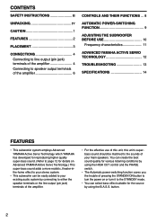
... and the PHASE switch. • The Automatic power-switching function saves you the trouble of your main speakers. button. 2 CONTENTS SAFETY INSTRUCTIONS II UNPACKING IV CAUTION 1 FEATURES 2 PLACEMENT 3 CONNECTIONS 4 Connecting to line output (pin jack) terminals of the amplifier 4 Connecting to speaker output terminals of the amplifier 6 CONTROLS AND THEIR FUNCTIONS ... 8 AUTOMATIC POWER-SWITCHING FUNCTION 9 ADJUSTING THE SUBWOOFER BEFORE USE 10 Frequency characteristics 11 ADVANCED YAMAHA ACTIVE SERVO TECHNOLOGY 12 TROUBLESHOOTING 13 SPECIFICATIONS 14 FEATURES •...
... and the PHASE switch. • The Automatic power-switching function saves you the trouble of your main speakers. button. 2 CONTENTS SAFETY INSTRUCTIONS II UNPACKING IV CAUTION 1 FEATURES 2 PLACEMENT 3 CONNECTIONS 4 Connecting to line output (pin jack) terminals of the amplifier 4 Connecting to speaker output terminals of the amplifier 6 CONTROLS AND THEIR FUNCTIONS ... 8 AUTOMATIC POWER-SWITCHING FUNCTION 9 ADJUSTING THE SUBWOOFER BEFORE USE 10 Frequency characteristics 11 ADVANCED YAMAHA ACTIVE SERVO TECHNOLOGY 12 TROUBLESHOOTING 13 SPECIFICATIONS 14 FEATURES •...
Owner's Manual
Page 7
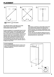
...; Ç ( : subwoofer, : main speaker) One subwoofer will have been developed between two parallel walls and they cancel the bass sounds. Note There may be necessary to break up the parallel surfaces by vibrations etc. 3 It also may die because the sound from the subwoofer when listening in the center of two subwoofers is recommended to obtain more effect. Use the...
...; Ç ( : subwoofer, : main speaker) One subwoofer will have been developed between two parallel walls and they cancel the bass sounds. Note There may be necessary to break up the parallel surfaces by vibrations etc. 3 It also may die because the sound from the subwoofer when listening in the center of two subwoofers is recommended to obtain more effect. Use the...
Owner's Manual
Page 8
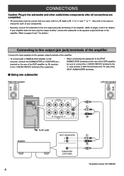
.... CONNECTIONS Caution: Plug in the subwoofer and other audio/video components after all connections are completed. • All connections must be sure to connect the L/MONO INPUT2 terminal to the "L" side and the R INPUT2 terminal to "-". I Using one subwoofer Right main speaker Left main speaker Subwoofer OUTPUT INPUT AUTO PHASE + T-O SPEAKER-S 2 STANDBY + /MONO + - - + OFF HIGH LOW NORM REV FROM AMPLIFIER INPUT 1 POWER ON OFF OUTPUT INPUT + T-O SPEAKER-S 2 + /MONO + - - + FROM AMPLIFIER INPUT 1 Amplifier To AC outlet SPLIT SUBWOOFER SUBWOOFER (LOW PASS...
.... CONNECTIONS Caution: Plug in the subwoofer and other audio/video components after all connections are completed. • All connections must be sure to connect the L/MONO INPUT2 terminal to the "L" side and the R INPUT2 terminal to "-". I Using one subwoofer Right main speaker Left main speaker Subwoofer OUTPUT INPUT AUTO PHASE + T-O SPEAKER-S 2 STANDBY + /MONO + - - + OFF HIGH LOW NORM REV FROM AMPLIFIER INPUT 1 POWER ON OFF OUTPUT INPUT + T-O SPEAKER-S 2 + /MONO + - - + FROM AMPLIFIER INPUT 1 Amplifier To AC outlet SPLIT SUBWOOFER SUBWOOFER (LOW PASS...
Owner's Manual
Page 9
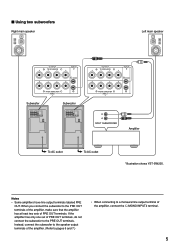
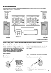
... set of PRE OUT terminals, do not connect the subwoofer to a monaural line output terminal of PRE OUT terminals. I Using two subwoofers Right main speaker Left main speaker OUTPUT INPUT + T-O SPEAKER-S 2 + /MONO + - - + FROM AMPLIFIER INPUT 1 Subwoofer Subwoofer OUTPUT INPUT AUTO PHASE + T-O SPEAKER-S 2 STANDBY + /MONO + - - + OFF HIGH LOW NORM REV FROM AMPLIFIER INPUT 1 POWER ON OFF OUTPUT INPUT AUTO PHASE + T-O SPEAKER-S 2 STANDBY + /MONO + - - + OFF HIGH LOW NORM REV FROM AMPLIFIER INPUT 1 POWER ON OFF OUTPUT INPUT + T-O SPEAKER...
... set of PRE OUT terminals, do not connect the subwoofer to a monaural line output terminal of PRE OUT terminals. I Using two subwoofers Right main speaker Left main speaker OUTPUT INPUT + T-O SPEAKER-S 2 + /MONO + - - + FROM AMPLIFIER INPUT 1 Subwoofer Subwoofer OUTPUT INPUT AUTO PHASE + T-O SPEAKER-S 2 STANDBY + /MONO + - - + OFF HIGH LOW NORM REV FROM AMPLIFIER INPUT 1 POWER ON OFF OUTPUT INPUT AUTO PHASE + T-O SPEAKER-S 2 STANDBY + /MONO + - - + OFF HIGH LOW NORM REV FROM AMPLIFIER INPUT 1 POWER ON OFF OUTPUT INPUT + T-O SPEAKER...
Owner's Manual
Page 10
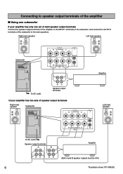
... shows YST-SW205. Connecting to speaker output terminals of the amplifier I Using one subwoofer If your amplifier has two sets of the subwoofer to the main speakers. Right main speaker Left main speaker Subwoofer OUTPUT INPUT AUTO PHASE + T-O SPEAKER-S 2 STANDBY + /MONO + - - + OFF HIGH LOW NORM REV FROM AMPLIFIER INPUT 1 POWER ON OFF OUTPUT INPUT + T-O SPEAKER-S 2 + /MONO + - - + FROM AMPLIFIER INPUT 1 Amplifier To AC outlet Speaker output terminals If your amplifier has only one set of main speaker output terminals Connect the speaker output...
... shows YST-SW205. Connecting to speaker output terminals of the amplifier I Using one subwoofer If your amplifier has two sets of the subwoofer to the main speakers. Right main speaker Left main speaker Subwoofer OUTPUT INPUT AUTO PHASE + T-O SPEAKER-S 2 STANDBY + /MONO + - - + OFF HIGH LOW NORM REV FROM AMPLIFIER INPUT 1 POWER ON OFF OUTPUT INPUT + T-O SPEAKER-S 2 + /MONO + - - + FROM AMPLIFIER INPUT 1 Amplifier To AC outlet Speaker output terminals If your amplifier has only one set of main speaker output terminals Connect the speaker output...
Owner's Manual
Page 11
... Connect: Red: positive (+) Black: negative (-) Banana Plug connections are also possible. 1 Loosen the knob. 2 Insert the bare wire. [Remove the insulation coating at the extremity of the cables. Right main speaker Left main speaker Subwoofer OUTPUT INPUT AUTO PHASE + T-O SPEAKER-S 2 STANDBY + /MONO + - - + OFF HIGH LOW NORM REV FROM AMPLIFIER INPUT 1 POWER ON OFF OUTPUT INPUT + T-O SPEAKER-S 2 + /MONO + - - + FROM AMPLIFIER INPUT 1 OUTPUT INPUT + T-O SPEAKER-S 2 + /MONO + - - + FROM AMPLIFIER INPUT 1 Amplifier Subwoofer OUTPUT INPUT AUTO...
... Connect: Red: positive (+) Black: negative (-) Banana Plug connections are also possible. 1 Loosen the knob. 2 Insert the bare wire. [Remove the insulation coating at the extremity of the cables. Right main speaker Left main speaker Subwoofer OUTPUT INPUT AUTO PHASE + T-O SPEAKER-S 2 STANDBY + /MONO + - - + OFF HIGH LOW NORM REV FROM AMPLIFIER INPUT 1 POWER ON OFF OUTPUT INPUT + T-O SPEAKER-S 2 + /MONO + - - + FROM AMPLIFIER INPUT 1 OUTPUT INPUT + T-O SPEAKER-S 2 + /MONO + - - + FROM AMPLIFIER INPUT 1 Amplifier Subwoofer OUTPUT INPUT AUTO...
Owner's Manual
Page 12
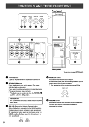
... bass sound in audio software is turned on. Ÿ STANDBY/ON button Press this mode. ! Standby mode The subwoofer is still using a small amount of this button is pressed in to set the subwoofer in the standby mode. (The power indicator does not light.) * This button can be used only when the POWER (%) switch is set in green while the subwoofer is well reproduced. MOVIE MUSIC 8 ON MOVIE MUSIC HIGH CUT VOLUME Front panel SUPERWOOFER SYSTEM YST-SW205 STANDBY/ B.A.S.S. Frequencies higher...
... bass sound in audio software is turned on. Ÿ STANDBY/ON button Press this mode. ! Standby mode The subwoofer is still using a small amount of this button is pressed in to set the subwoofer in the standby mode. (The power indicator does not light.) * This button can be used only when the POWER (%) switch is set in green while the subwoofer is well reproduced. MOVIE MUSIC 8 ON MOVIE MUSIC HIGH CUT VOLUME Front panel SUPERWOOFER SYSTEM YST-SW205 STANDBY/ B.A.S.S. Frequencies higher...
Owner's Manual
Page 13
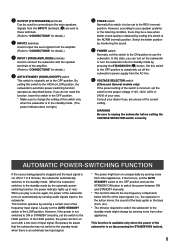
... or 240V) of low frequency input signal. Signals from the amplifier. (Refer to "CONNECTIONS" for details.) $ AUTO STANDBY (HIGH/LOW/OFF) switch This switch is on even with the speaker terminals of the amplifier. (Refer to "CONNECTIONS" for details.) ‹ INPUT1 (FROM AMPLIFIER) terminals Used to connect the subwoofer with a low level of the correct setting. However, according to your area. AUTOMATIC POWER-SWITCHING FUNCTION If the source being played is stopped and the input signal is obtained by...
... or 240V) of low frequency input signal. Signals from the amplifier. (Refer to "CONNECTIONS" for details.) $ AUTO STANDBY (HIGH/LOW/OFF) switch This switch is on even with the speaker terminals of the amplifier. (Refer to "CONNECTIONS" for details.) ‹ INPUT1 (FROM AMPLIFIER) terminals Used to connect the subwoofer with a low level of the correct setting. However, according to your area. AUTOMATIC POWER-SWITCHING FUNCTION If the source being played is stopped and the input signal is obtained by...
Owner's Manual
Page 14
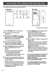
... this adjustment again. • For adjusting the VOLUME control, the HIGH CUT control and the PHASE switch, refer to the played source. If the desired response cannot be obtained, set the switch to minimum (0). 2 Turn on the next page. 10 ON MOVIE MUSIC HIGH CUT VOLUME 40Hz 140Hz 0 10 3 8 5 1, 6 Rear panel OUTPUT INPUT AUTO PHASE + T-O SPEAKER-S 2 STANDBY + /MONO + - - + OFF HIGH LOW NORM REV FROM AMPLIFIER INPUT 1 POWER ON OFF PHASE NORM REV 7 1 Set the VOLUME control to...
... this adjustment again. • For adjusting the VOLUME control, the HIGH CUT control and the PHASE switch, refer to the played source. If the desired response cannot be obtained, set the switch to minimum (0). 2 Turn on the next page. 10 ON MOVIE MUSIC HIGH CUT VOLUME 40Hz 140Hz 0 10 3 8 5 1, 6 Rear panel OUTPUT INPUT AUTO PHASE + T-O SPEAKER-S 2 STANDBY + /MONO + - - + OFF HIGH LOW NORM REV FROM AMPLIFIER INPUT 1 POWER ON OFF PHASE NORM REV 7 1 Set the VOLUME control to...
Owner's Manual
Page 15
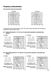
... 40 20 50 100 200 500Hz The figures below show the optimum adjustment of each control and the frequency characteristics when this subwoofer is combined with an 8" or 10" (20 cm or 25 cm) acoustic suspension, 2 way system main speakers YST-SW305 HIGH CUT VOLUME dB Combined frequency response 90 80 40Hz 140Hz 0 10 70 * One graduation of this...
... 40 20 50 100 200 500Hz The figures below show the optimum adjustment of each control and the frequency characteristics when this subwoofer is combined with an 8" or 10" (20 cm or 25 cm) acoustic suspension, 2 way system main speakers YST-SW305 HIGH CUT VOLUME dB Combined frequency response 90 80 40Hz 140Hz 0 10 70 * One graduation of this...
Owner's Manual
Page 16
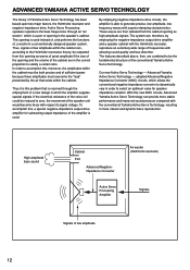
... designed speaker system. adopted Advanced Negative Impedance Converter (ANIC) circuits, which is this new ANIC circuits, Advanced Yamaha Active Servo Technology can provide more natural and dynamic bass reproduction. High-amplitude bass sound Cabinet Port Advanced Negativeimpedance Converter Active Servo Processing Amplifier Air woofer (Helmholtz resonator) Signals Signals of frequencies with amazing sound quality and less distortion. Active Servo Processing speakers reproduce the bass frequencies through...
... designed speaker system. adopted Advanced Negative Impedance Converter (ANIC) circuits, which is this new ANIC circuits, Advanced Yamaha Active Servo Technology can provide more natural and dynamic bass reproduction. High-amplitude bass sound Cabinet Port Advanced Negativeimpedance Converter Active Servo Processing Amplifier Air woofer (Helmholtz resonator) Signals Signals of frequencies with amazing sound quality and less distortion. Active Servo Processing speakers reproduce the bass frequencies through...
Owner's Manual
Page 17
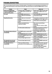
... do not help, disconnect the power cable and contact your authorized YAMAHA dealer or service center. If the problem you are experiencing is L (left) to L, R (right) to R, "+" to "+" and "-" to "-". Problem Power is not supplied even though the STANDBY/ON button is not proper. No sound. The subwoofer does not turn on unexpectedly. Setting of input signal is set to the "OFF" position. 13 The AUTO STANDBY switch is set the AUTO STANDBY switch to...
... do not help, disconnect the power cable and contact your authorized YAMAHA dealer or service center. If the problem you are experiencing is L (left) to L, R (right) to R, "+" to "+" and "-" to "-". Problem Power is not supplied even though the STANDBY/ON button is not proper. No sound. The subwoofer does not turn on unexpectedly. Setting of input signal is set to the "OFF" position. 13 The AUTO STANDBY switch is set the AUTO STANDBY switch to...
Owner's Manual
Page 18
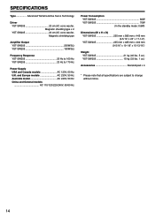
... that all specifications are subject to 170 Hz Power Supply USA and Canada models AC 120V, 60 Hz U.K. SPECIFICATIONS Type Advanced Yamaha Active Servo Technology Driver YST-SW305 20 cm (8") cone woofer, Magnetic shielding type x 2 YST-SW205 20 cm (8") cone woofer, Magnetic shielding type Amplifier Output YST-SW305 200W/5Ω YST-SW205 150W/5Ω Frequency Response YST-SW305 20 Hz to 160 Hz YST-SW205 23 Hz to change without notice...
... that all specifications are subject to 170 Hz Power Supply USA and Canada models AC 120V, 60 Hz U.K. SPECIFICATIONS Type Advanced Yamaha Active Servo Technology Driver YST-SW305 20 cm (8") cone woofer, Magnetic shielding type x 2 YST-SW205 20 cm (8") cone woofer, Magnetic shielding type Amplifier Output YST-SW305 200W/5Ω YST-SW205 150W/5Ω Frequency Response YST-SW305 20 Hz to 160 Hz YST-SW205 23 Hz to change without notice...

Owner's Manual
Page 19
...-33 MARKET ST., SOUTH MELBOURNE, 3205 VIC., AUSTRALIA Printed in Indonesia V731310-1 OF GERMANY YAMAHA ELECTRONIQUE FRANCE S.A. YAMAHA HOUSE, 200 RICKMANSWORTH ROAD WATFORD, HERTS WD1 7JS, ENGLAND YAMAHA SCANDINAVIA A.B. YAMAHA CANADA MUSIC LTD. 135 MILNER AVE., SCARBOROUGH, ONTARIO M1S 3R1, CANADA YAMAHA ELECTRONIK EUROPA G.m.b.H. RUE AMBROISE CROIZAT BP70 CROISSY-BEAUBOURG 77312 MARNE-LA-VALLEE CEDEX02, FRANCE...
...-33 MARKET ST., SOUTH MELBOURNE, 3205 VIC., AUSTRALIA Printed in Indonesia V731310-1 OF GERMANY YAMAHA ELECTRONIQUE FRANCE S.A. YAMAHA HOUSE, 200 RICKMANSWORTH ROAD WATFORD, HERTS WD1 7JS, ENGLAND YAMAHA SCANDINAVIA A.B. YAMAHA CANADA MUSIC LTD. 135 MILNER AVE., SCARBOROUGH, ONTARIO M1S 3R1, CANADA YAMAHA ELECTRONIK EUROPA G.m.b.H. RUE AMBROISE CROIZAT BP70 CROISSY-BEAUBOURG 77312 MARNE-LA-VALLEE CEDEX02, FRANCE...


