
Owner's Manual
Page 5
... an electric shock. ● Do not place this unit where foreign objects such as this might also cause personal injury and/or damage to this YAMAHA Subwoofer System. This unit's power supply is completely cut off by not following the cautions below. ● To assure the finest performance, please read this unit... to be used must be the same as it too close to this unit, and/or personal injury. ● Never place a fragile object near the YST port of at high volume level. falls by vibrations and water spills, it may be liable for any damage and/or injury caused by pressing...
... an electric shock. ● Do not place this unit where foreign objects such as this might also cause personal injury and/or damage to this YAMAHA Subwoofer System. This unit's power supply is completely cut off by not following the cautions below. ● To assure the finest performance, please read this unit... to be used must be the same as it too close to this unit, and/or personal injury. ● Never place a fragile object near the YST port of at high volume level. falls by vibrations and water spills, it may be liable for any damage and/or injury caused by pressing...
Owner's Manual
Page 6
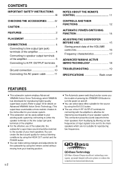
...the sounds of input signals to be sent to the main speakers which YAMAHA has developed for reproducing higher quality super-bass sound. (Refer to your stereo system. ● This subwoofer can select bass effect suitable for reproducing low frequencies. This connection prevents... Storing preset data of the VOLUME control etc 16 Frequency characteristics 17 ADVANCED YAMAHA ACTIVE SERVO TECHNOLOGY 18 TROUBLESHOOTING 19 SPECIFICATIONS Back cover FEATURES ● This subwoofer system employs Advanced YAMAHA Active Servo Technology which are not suitable for the source by connecting to...
...the sounds of input signals to be sent to the main speakers which YAMAHA has developed for reproducing higher quality super-bass sound. (Refer to your stereo system. ● This subwoofer can select bass effect suitable for reproducing low frequencies. This connection prevents... Storing preset data of the VOLUME control etc 16 Frequency characteristics 17 ADVANCED YAMAHA ACTIVE SERVO TECHNOLOGY 18 TROUBLESHOOTING 19 SPECIFICATIONS Back cover FEATURES ● This subwoofer system employs Advanced YAMAHA Active Servo Technology which are not suitable for the source by connecting to...
Owner's Manual
Page 7
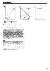
...center of the room. along the walls. It also may be a case that you cannot obtain enough superbass sounds from happening, face the subwoofer system at an angle as in fig. Å or ı. Note There may be necessary to obtain more effect. This is recommended... main speaker. (See fig. Å.) If using one subwoofer, it is recommended to the wall. PLACEMENT Å ı Ç ( : subwoofer, : main speaker) One subwoofer will have a good effect on your audio system, however, the use of two subwoofers is because "standing waves" have been developed between two parallel...
...center of the room. along the walls. It also may be a case that you cannot obtain enough superbass sounds from happening, face the subwoofer system at an angle as in fig. Å or ı. Note There may be necessary to obtain more effect. This is recommended... main speaker. (See fig. Å.) If using one subwoofer, it is recommended to the wall. PLACEMENT Å ı Ç ( : subwoofer, : main speaker) One subwoofer will have a good effect on your audio system, however, the use of two subwoofers is because "standing waves" have been developed between two parallel...
Owner's Manual
Page 8
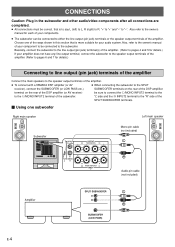
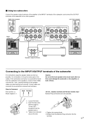
...INPUT 3 2 OUTPUT TO SPEAKERS FROM AMPLIFIER INPUT 1 Mono pin cable (not included) Audio pin cable (not included) Amplifier SPLIT SUBWOOFER SUBWOOFER (LOW PASS) E-4 Basically, connect the subwoofer to the line output (pin jack) terminal(s) of the amplifier. (Refer to pages 4 and 5 for details.) If your ...main speakers to the speaker output terminals of the amplifier. ● To connect with a YAMAHA DSP amplifier (or AV ● When connecting the subwoofer to the SPLIT receiver), connect the SUBWOOFER (or LOW PASS etc.) terminal on the rear of the DSP amplifier, be sure to ...
...INPUT 3 2 OUTPUT TO SPEAKERS FROM AMPLIFIER INPUT 1 Mono pin cable (not included) Audio pin cable (not included) Amplifier SPLIT SUBWOOFER SUBWOOFER (LOW PASS) E-4 Basically, connect the subwoofer to the line output (pin jack) terminal(s) of the amplifier. (Refer to pages 4 and 5 for details.) If your ...main speakers to the speaker output terminals of the amplifier. ● To connect with a YAMAHA DSP amplifier (or AV ● When connecting the subwoofer to the SPLIT receiver), connect the SUBWOOFER (or LOW PASS etc.) terminal on the rear of the DSP amplifier, be sure to ...
Owner's Manual
Page 9
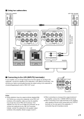
...80Hz 100Hz LFE NORMAL /MONO OUTPUT H.P.F.OUTPUT TO SPEAKERS 80Hz 100Hz LFE NORMAL /MONO OUTPUT TO SPEAKERS GND INPUT INPUT 3 2 Right subwoofer REMOTE AUTO STANDBY OUTPUT INPUT HIGH LOW OFF H.P.F.OUTPUT 80Hz 100Hz LFE NORMAL /MONO GND INPUT INPUT 3 2 OUTPUT TO SPEAKERS FROM AMPLIFIER... INPUT 1 GND FROM AMPLIFIER INPUT 1 Left subwoofer REMOTE AUTO STANDBY OUTPUT INPUT HIGH LOW OFF H.P.F.OUTPUT 80Hz 100Hz LFE NORMAL /MONO GND INPUT INPUT 3 2 OUTPUT TO SPEAKERS FROM ...
...80Hz 100Hz LFE NORMAL /MONO OUTPUT H.P.F.OUTPUT TO SPEAKERS 80Hz 100Hz LFE NORMAL /MONO OUTPUT TO SPEAKERS GND INPUT INPUT 3 2 Right subwoofer REMOTE AUTO STANDBY OUTPUT INPUT HIGH LOW OFF H.P.F.OUTPUT 80Hz 100Hz LFE NORMAL /MONO GND INPUT INPUT 3 2 OUTPUT TO SPEAKERS FROM AMPLIFIER... INPUT 1 GND FROM AMPLIFIER INPUT 1 Left subwoofer REMOTE AUTO STANDBY OUTPUT INPUT HIGH LOW OFF H.P.F.OUTPUT 80Hz 100Hz LFE NORMAL /MONO GND INPUT INPUT 3 2 OUTPUT TO SPEAKERS FROM ...

Owner's Manual
Page 10
...terminals of the amplifier Ⅵ Using one subwoofer If your amplifier has two sets of the subwoofer to the INPUT1 terminals of the subwoofer, and connect the OUTPUT terminals of speaker output terminals Right main speaker Subwoofer REMOTE AUTO STANDBY OUTPUT INPUT HIGH LOW OFF... Amplifier (Both A and B speaker outputs must be ON.) E-6 Right main speaker Left main speaker H.P.F.OUTPUT 80Hz 100Hz LFE NORMAL /MONO Subwoofer REMOTE AUTO STANDBY HIGH OFF OUTPUT INPUT LOW H.P.F.OUTPUT 80Hz 100Hz LFE NORMAL /MONO GND INPUT INPUT 3 2 OUTPUT TO SPEAKERS FROM AMPLIFIER...
...terminals of the amplifier Ⅵ Using one subwoofer If your amplifier has two sets of the subwoofer to the INPUT1 terminals of the subwoofer, and connect the OUTPUT terminals of speaker output terminals Right main speaker Subwoofer REMOTE AUTO STANDBY OUTPUT INPUT HIGH LOW OFF... Amplifier (Both A and B speaker outputs must be ON.) E-6 Right main speaker Left main speaker H.P.F.OUTPUT 80Hz 100Hz LFE NORMAL /MONO Subwoofer REMOTE AUTO STANDBY HIGH OFF OUTPUT INPUT LOW H.P.F.OUTPUT 80Hz 100Hz LFE NORMAL /MONO GND INPUT INPUT 3 2 OUTPUT TO SPEAKERS FROM AMPLIFIER...
Owner's Manual
Page 11
...OUTPUT TO SPEAKERS 80Hz 100Hz LFE NORMAL /MONO GND FROM AMPLIFIER INPUT 1 INPUT INPUT 3 2 OUTPUT TO SPEAKERS FROM AMPLIFIER INPUT 1 Amplifier Left subwoofer REMOTE AUTO STANDBY OUTPUT INPUT HIGH LOW OFF H.P.F.OUTPUT 80Hz 100Hz LFE NORMAL /MONO GND INPUT INPUT 3 2 OUTPUT TO SPEAKERS FROM AMPLIFIER INPUT 1... the Banana Plug connector into the terminal. How to the main speakers. E-7 Do not bundle or roll up the excess part of the subwoofer to Connect: Red: positive (+) Black: negative (-) Caution Do not let the bare speaker wires touch each other as possible. If these ...
...OUTPUT TO SPEAKERS 80Hz 100Hz LFE NORMAL /MONO GND FROM AMPLIFIER INPUT 1 INPUT INPUT 3 2 OUTPUT TO SPEAKERS FROM AMPLIFIER INPUT 1 Amplifier Left subwoofer REMOTE AUTO STANDBY OUTPUT INPUT HIGH LOW OFF H.P.F.OUTPUT 80Hz 100Hz LFE NORMAL /MONO GND INPUT INPUT 3 2 OUTPUT TO SPEAKERS FROM AMPLIFIER INPUT 1... the Banana Plug connector into the terminal. How to the main speakers. E-7 Do not bundle or roll up the excess part of the subwoofer to Connect: Red: positive (+) Black: negative (-) Caution Do not let the bare speaker wires touch each other as possible. If these ...

Owner's Manual
Page 12
...you are using separate amplifiers (pre-amplifier and main amplifier). Ⅵ To connect one unit only Right main speaker Left main speaker Subwoofer REMOTE AUTO STANDBY OUTPUT INPUT HIGH LOW OFF H.P.F.OUTPUT 80Hz 100Hz LFE NORMAL /MONO GND INPUT INPUT 3 2 OUTPUT TO SPEAKERS FROM ...OUTPUT TO SPEAKERS FROM AMPLIFIER INPUT 1 Audio pin cable (not included) PRE OUT MAIN IN Amplifier E-8 OUTPUT terminals The use of the subwoofer cut off frequencies below the selected frequency point from the input signals, and output high frequencies only. Connecting to H.P.F. The H.P.F. (High-...
...you are using separate amplifiers (pre-amplifier and main amplifier). Ⅵ To connect one unit only Right main speaker Left main speaker Subwoofer REMOTE AUTO STANDBY OUTPUT INPUT HIGH LOW OFF H.P.F.OUTPUT 80Hz 100Hz LFE NORMAL /MONO GND INPUT INPUT 3 2 OUTPUT TO SPEAKERS FROM ...OUTPUT TO SPEAKERS FROM AMPLIFIER INPUT 1 Audio pin cable (not included) PRE OUT MAIN IN Amplifier E-8 OUTPUT terminals The use of the subwoofer cut off frequencies below the selected frequency point from the input signals, and output high frequencies only. Connecting to H.P.F. The H.P.F. (High-...

Owner's Manual
Page 13
...included) H.P.F.OUTPUT 80Hz 100Hz LFE NORMAL /MONO OUTPUT TO SPEAKERS H.P.F.OUTPUT 80Hz 100Hz LFE NORMAL /MONO OUTPUT TO SPEAKERS GND Right subwoofer REMOTE AUTO STANDBY OUTPUT INPUT HIGH LOW OFF H.P.F.OUTPUT 80Hz 100Hz LFE NORMAL /MONO GND INPUT INPUT 3 2 OUTPUT TO SPEAKERS ...FROM AMPLIFIER INPUT 1 INPUT INPUT 3 2 GND FROM AMPLIFIER INPUT 1 Left subwoofer REMOTE AUTO STANDBY OUTPUT INPUT HIGH LOW OFF H.P.F.OUTPUT 80Hz 100Hz LFE NORMAL /MONO GND INPUT INPUT 3 2 OUTPUT TO SPEAKERS FROM AMPLIFIER ...
...included) H.P.F.OUTPUT 80Hz 100Hz LFE NORMAL /MONO OUTPUT TO SPEAKERS H.P.F.OUTPUT 80Hz 100Hz LFE NORMAL /MONO OUTPUT TO SPEAKERS GND Right subwoofer REMOTE AUTO STANDBY OUTPUT INPUT HIGH LOW OFF H.P.F.OUTPUT 80Hz 100Hz LFE NORMAL /MONO GND INPUT INPUT 3 2 OUTPUT TO SPEAKERS ...FROM AMPLIFIER INPUT 1 INPUT INPUT 3 2 GND FROM AMPLIFIER INPUT 1 Left subwoofer REMOTE AUTO STANDBY OUTPUT INPUT HIGH LOW OFF H.P.F.OUTPUT 80Hz 100Hz LFE NORMAL /MONO GND INPUT INPUT 3 2 OUTPUT TO SPEAKERS FROM AMPLIFIER ...

Owner's Manual
Page 14
Subwoofer Insert Tighten Grounding cable REMOTE AUTO STANDBY HIGH OFF OUTPUT INPUT LOW H.P.F.OUTPUT 80Hz 100Hz LFE NORMAL /MONO GND INPUT INPUT 3 2 OUTPUT TO SPEAKERS FROM ...) MD 4 OUT (REC) AUX PRE OUT MAIN IN Receiver/amplifier E-10 Ground connection If there is a humming noise when using the subwoofer connected to the speaker terminals, connect the subwoofer and the receiver/amplifier with the grounding cable as shown in Illustration A. * If there is no ground terminal (GND) on the receiver...
Subwoofer Insert Tighten Grounding cable REMOTE AUTO STANDBY HIGH OFF OUTPUT INPUT LOW H.P.F.OUTPUT 80Hz 100Hz LFE NORMAL /MONO GND INPUT INPUT 3 2 OUTPUT TO SPEAKERS FROM ...) MD 4 OUT (REC) AUX PRE OUT MAIN IN Receiver/amplifier E-10 Ground connection If there is a humming noise when using the subwoofer connected to the speaker terminals, connect the subwoofer and the receiver/amplifier with the grounding cable as shown in Illustration A. * If there is no ground terminal (GND) on the receiver...

Owner's Manual
Page 15
... If the remote control sensor is directly illuminated by strong lighting (especially an inverter type of them immediately. Otherwise, it come in the subwoofer to the main unit, the batteries are weak. Plug in contact with new ones. Clean the battery compartment thoroughly before installing new batteries. ... of fluorescent lamp etc.), it might cause the remote control not to any power cable other unit than the included one to the subwoofer. Replace both batteries with clothing, etc. Avoid touching the leaked material or letting it may result in the power cable to avoid ...
... If the remote control sensor is directly illuminated by strong lighting (especially an inverter type of them immediately. Otherwise, it come in the subwoofer to the main unit, the batteries are weak. Plug in contact with new ones. Clean the battery compartment thoroughly before installing new batteries. ... of fluorescent lamp etc.), it might cause the remote control not to any power cable other unit than the included one to the subwoofer. Replace both batteries with clothing, etc. Avoid touching the leaked material or letting it may result in the power cable to avoid ...

Owner's Manual
Page 16
...UP/DOWN buttons Select the upper limit of power in the standby mode. * This button can be reproduced by the subwoofer. CONTROLS AND THEIR FUNCTIONS Front panel SUBWOOFER SYSTEM YST-SW1500 PRESET MUSIC/MOVIE PHASE 1 2 3 STANDBY/ON B.A.S.S. By pressing this switch to select the MUSIC mode, the ... this switch to set the subwoofer in this button to be used only when the POWER (A) switch is set in video software is still using a small amount of the frequencies to turn it. HIGH CUT VOLUME 40Hz 14Hz 0 10 5 6 78 9 SUBWOOFER SYSTEM YST-SW1500 PRESET MUSIC/MOVIE PHASE 1 ...
...UP/DOWN buttons Select the upper limit of power in the standby mode. * This button can be reproduced by the subwoofer. CONTROLS AND THEIR FUNCTIONS Front panel SUBWOOFER SYSTEM YST-SW1500 PRESET MUSIC/MOVIE PHASE 1 2 3 STANDBY/ON B.A.S.S. By pressing this switch to select the MUSIC mode, the ... this switch to set the subwoofer in this button to be used only when the POWER (A) switch is set in video software is still using a small amount of the frequencies to turn it. HIGH CUT VOLUME 40Hz 14Hz 0 10 5 6 78 9 SUBWOOFER SYSTEM YST-SW1500 PRESET MUSIC/MOVIE PHASE 1 ...
Owner's Manual
Page 17
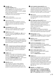
... (TO SPEAKERS) terminals Can be a case when better sound quality is connected to the OFF position. OUTPUT terminals These terminals cut off the subwoofer's power supply from the remote control. 6 Power indicator (LED) Lights up in the OFF position. F INPUT3 (LFE) terminals The HIGH CUT... connecting with the speaker terminals of these terminals. (Refer to "CONNECTIONS" for details.) I INPUT1 (FROM AMPLIFIER) terminals Used to connect the subwoofer with the amplifier. (See page 8 for details.) J PHASE button Normally press this switch to the OFF position to another unit. K MEMORY...
... (TO SPEAKERS) terminals Can be a case when better sound quality is connected to the OFF position. OUTPUT terminals These terminals cut off the subwoofer's power supply from the remote control. 6 Power indicator (LED) Lights up in the OFF position. F INPUT3 (LFE) terminals The HIGH CUT... connecting with the speaker terminals of these terminals. (Refer to "CONNECTIONS" for details.) I INPUT1 (FROM AMPLIFIER) terminals Used to connect the subwoofer with the amplifier. (See page 8 for details.) J PHASE button Normally press this switch to the OFF position to another unit. K MEMORY...

Owner's Manual
Page 18
... the source being played is stopped and the input signal is cut off .) E-14 In the HIGH position, the power will not work if the subwoofer is turned into the standby mode by sensing noise from other appliances. This function will turn on unexpectedly by using the STANDBY/ON button. (The... of the input signals (i.e., the explosion in red.) When you play a source again, the power of the subwoofer turns on (by setting the STANDBY/ON button to the LOW position. If that the subwoofer may not switch to the standby mode when there is not switched to ON or STANDBY smoothly, set...
... the source being played is stopped and the input signal is cut off .) E-14 In the HIGH position, the power will not work if the subwoofer is turned into the standby mode by sensing noise from other appliances. This function will turn on unexpectedly by using the STANDBY/ON button. (The... of the input signals (i.e., the explosion in red.) When you play a source again, the power of the subwoofer turns on (by setting the STANDBY/ON button to the LOW position. If that the subwoofer may not switch to the standby mode when there is not switched to ON or STANDBY smoothly, set...
Owner's Manual
Page 19
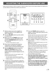
... and adjust the amplifier's volume control to obtain the optimum volume and tone balance between the subwoofer and the main speakers by following the procedures described below. 3 8 5 7 6 SUBWOOFER SYSTEM YST-SW1500 PRESET MUSIC/MOVIE PHASE 1 2 3 STANDBY/ON B.A.S.S. Normally, set the control to the ... cannot be obtained, select the regular mode (so that the POWER switch on page 17. HIGH CUT VOLUME 40Hz 14Hz 0 10 SUBWOOFER SYSTEM YST-SW1500 PRESET MUSIC/MOVIE PHASE 1 2 3 STANDBY/ON B.A.S.S. Normally, select the reverse mode (so that the PHASE indicator on the remote...
... and adjust the amplifier's volume control to obtain the optimum volume and tone balance between the subwoofer and the main speakers by following the procedures described below. 3 8 5 7 6 SUBWOOFER SYSTEM YST-SW1500 PRESET MUSIC/MOVIE PHASE 1 2 3 STANDBY/ON B.A.S.S. Normally, set the control to the ... cannot be obtained, select the regular mode (so that the POWER switch on page 17. HIGH CUT VOLUME 40Hz 14Hz 0 10 SUBWOOFER SYSTEM YST-SW1500 PRESET MUSIC/MOVIE PHASE 1 2 3 STANDBY/ON B.A.S.S. Normally, select the reverse mode (so that the PHASE indicator on the remote...
Owner's Manual
Page 20
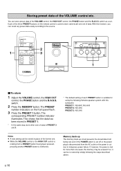
... or the power is used to temporary power failure. You can be re-stored by simply following Yamaha speaker system with this function, you can be erased. With this subwoofer. Storing preset data of data. This shows that the data has been stored in PRESET 1. *...10 1 Ⅵ To store 1 Adjust the VOLUME control, the HIGH CUT control, the PHASE button and the B.A.S.S. HIGH CUT VOLUME 40Hz 14Hz 0 10 3 SUBWOOFER SYSTEM YST-SW1500 PRESET MUSIC/MOVIE PHASE 1 2 3 STANDBY/ON B.A.S.S. PRESET 1: NS-8HX, NS-6HX PRESET 2: NS-4HX PRESET 3: NS-2HX Notes ● A new setting...
... or the power is used to temporary power failure. You can be re-stored by simply following Yamaha speaker system with this function, you can be erased. With this subwoofer. Storing preset data of data. This shows that the data has been stored in PRESET 1. *...10 1 Ⅵ To store 1 Adjust the VOLUME control, the HIGH CUT control, the PHASE button and the B.A.S.S. HIGH CUT VOLUME 40Hz 14Hz 0 10 3 SUBWOOFER SYSTEM YST-SW1500 PRESET MUSIC/MOVIE PHASE 1 2 3 STANDBY/ON B.A.S.S. PRESET 1: NS-8HX, NS-6HX PRESET 2: NS-4HX PRESET 3: NS-2HX Notes ● A new setting...

Owner's Manual
Page 21
B.A.S.S.-MOVIE 80 YST-SW1500 70 60 Main speaker's response 50 40 20 50 100 200 500 Hz EX...When combined with a typical main speaker system. B.A.S.S.-MOVIE 80 YST-SW1500 70 Main 60 speaker's response 50 40 20 50 100 200 500 Hz E-17 English Frequency characteristics This subwoofer's frequency characteristics 100 dB 90 80 70 HIGH CUT 40...50 100 200 500 Hz The figures below show the optimum adjustment of each control and the frequency characteristics when this subwoofer is combined with a 4" or 5" (10 cm or 13 cm) acoustic suspension, 2 way system main speakers ...
B.A.S.S.-MOVIE 80 YST-SW1500 70 60 Main speaker's response 50 40 20 50 100 200 500 Hz EX...When combined with a typical main speaker system. B.A.S.S.-MOVIE 80 YST-SW1500 70 Main 60 speaker's response 50 40 20 50 100 200 500 Hz E-17 English Frequency characteristics This subwoofer's frequency characteristics 100 dB 90 80 70 HIGH CUT 40...50 100 200 500 Hz The figures below show the optimum adjustment of each control and the frequency characteristics when this subwoofer is combined with a 4" or 5" (10 cm or 13 cm) acoustic suspension, 2 way system main speakers ...
Owner's Manual
Page 23
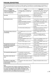
...set to a higher position. Set the AUTO STANDBY switch to the chart below do not help, disconnect the power cable and contact your authorized YAMAHA dealer or service center. Cause The power cable is set the AUTO STANDBY switch to the "HIGH" position. Speaker cables are not connected securely....from such appliances and/or reposition the connected speaker cables. There is an influence of the PHASE is set the POWER switch to the subwoofer. The subwoofer consumes much electricity when a high level signal is too low. What to Do Connect the power cable to the standby mode by ...
...set to a higher position. Set the AUTO STANDBY switch to the chart below do not help, disconnect the power cable and contact your authorized YAMAHA dealer or service center. Cause The power cable is set the AUTO STANDBY switch to the "HIGH" position. Speaker cables are not connected securely....from such appliances and/or reposition the connected speaker cables. There is an influence of the PHASE is set the POWER switch to the subwoofer. The subwoofer consumes much electricity when a high level signal is too low. What to Do Connect the power cable to the standby mode by ...


