

Owner's Manual
Page 1
Please record the serial number of this YAMAHA Subwoofer System. Active Servo Technology OWNER'S MANUAL CONTENTS Safety Instructions 2 Features 4 Placement 4 Connections 5 Controls and Their Functions .......8 Adjusting Volume 9 Active Servo Technology ........11 Troubleshooting 12 Specifications 12 IMPORTANT! The exclamation point within an equilateral triangle is intended to alert you to persons. Model: Serial No.: The serial number is intended to alert you to the presence of uninsulated...
Please record the serial number of this YAMAHA Subwoofer System. Active Servo Technology OWNER'S MANUAL CONTENTS Safety Instructions 2 Features 4 Placement 4 Connections 5 Controls and Their Functions .......8 Adjusting Volume 9 Active Servo Technology ........11 Troubleshooting 12 Specifications 12 IMPORTANT! The exclamation point within an equilateral triangle is intended to alert you to persons. Model: Serial No.: The serial number is intended to alert you to the presence of uninsulated...
Owner's Manual
Page 2
... on the unit and in performance; Also, do not position with the rear panel facing down on switches, controls or connection wires. In such a case, move this unit away from windows, heat sources, sources of the unit. 15 Damage Requiring Service - All warnings on the unit. 11 Power-Cord Protection - For example, the unit should be situated on or pinched by the...
... on the unit and in performance; Also, do not position with the rear panel facing down on switches, controls or connection wires. In such a case, move this unit away from windows, heat sources, sources of the unit. 15 Damage Requiring Service - All warnings on the unit. 11 Power-Cord Protection - For example, the unit should be situated on or pinched by the...
Owner's Manual
Page 3
This product, when installed as indicated in the instructions contained in FCC Regulations, Part 15 for Class "B" digital devices. Follow all installations. If the antenna lead-in is often undetectable until it at a safe level. FCC INFORMATION 1. Failure to follow instructions could void your FCC authorization to use the product. 2. This equipment generates/uses radio frequencies and, if not installed and used . If this product...
This product, when installed as indicated in the instructions contained in FCC Regulations, Part 15 for Class "B" digital devices. Follow all installations. If the antenna lead-in is often undetectable until it at a safe level. FCC INFORMATION 1. Failure to follow instructions could void your FCC authorization to use the product. 2. This equipment generates/uses radio frequencies and, if not installed and used . If this product...
Owner's Manual
Page 4
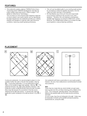
... placed directly facing the wall, the bass effect may be a case that you to select the best sound quality for details on the outside of either the speaker terminals or the line output (pin jack) terminals of the amplifier. • For the effective use of your main speakers. To prevent this unit employs a continuously variable high frequency cut-off point (HIGH CUT) control...
... placed directly facing the wall, the bass effect may be a case that you to select the best sound quality for details on the outside of either the speaker terminals or the line output (pin jack) terminals of the amplifier. • For the effective use of your main speakers. To prevent this unit employs a continuously variable high frequency cut-off point (HIGH CUT) control...

Owner's Manual
Page 5
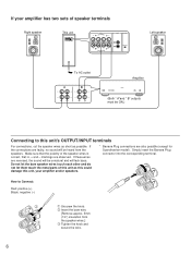
Also, refer to the owner's manual for each component to be connected to this unit. If using two units Right speaker This unit OUTPUT TO SPEAKERS FROM AMPLIFIER INPUT1 INPUT2 PHASE NOM REV OUTPUT TO SPEAKERS FROM AMPLIFIER INPUT1 INPUT2 PHASE NOM REV Left speaker OUTPUT TO SPEAKERS INPUT2 PHASE FROM AMPLIFIER INPUT1 NOM REV Amplifier This unit OUTPUT TO SPEAKERS FROM AMPLIFIER INPUT1 INPUT2 PHASE NOM REV To AC outlet...
Also, refer to the owner's manual for each component to be connected to this unit. If using two units Right speaker This unit OUTPUT TO SPEAKERS FROM AMPLIFIER INPUT1 INPUT2 PHASE NOM REV OUTPUT TO SPEAKERS FROM AMPLIFIER INPUT1 INPUT2 PHASE NOM REV Left speaker OUTPUT TO SPEAKERS INPUT2 PHASE FROM AMPLIFIER INPUT1 NOM REV Amplifier This unit OUTPUT TO SPEAKERS FROM AMPLIFIER INPUT1 INPUT2 PHASE NOM REV To AC outlet...
Owner's Manual
Page 6
... NOM REV OUTPUT TO SPEAKERS FROM AMPLIFIER INPUT1 INPUT2 PHASE NOM REV Left speaker To AC outlet A B Amplifier (Both " A"and " B" outputs must be unnatural and will lack bass. How to this unit's OUTPUT/INPUT terminals For connections, cut the speaker wires as short as this could damage this unit as possible. If these wires are reversed, the sound will be ON.) Connecting to Connect: Red: positive (+) Black...
... NOM REV OUTPUT TO SPEAKERS FROM AMPLIFIER INPUT1 INPUT2 PHASE NOM REV Left speaker To AC outlet A B Amplifier (Both " A"and " B" outputs must be unnatural and will lack bass. How to this unit's OUTPUT/INPUT terminals For connections, cut the speaker wires as short as this could damage this unit as possible. If these wires are reversed, the sound will be ON.) Connecting to Connect: Red: positive (+) Black...

Owner's Manual
Page 7
... on the rear panel of PRE OUT terminals. If using one set of the amplifier, connect to either the left and right speakers. CONNECTING TO LINE OUTPUT (PIN JACK) TERMINALS OF THE AMPLIFIER • Leave the main speakers connected to the amplifier. • Amplifier line output terminals are generally labeled PRE OUT or SUBWOOFER OUT. * For PRE OUT terminal connection, the amplifier must possess at least two sets of this case, select the method...
... on the rear panel of PRE OUT terminals. If using one set of the amplifier, connect to either the left and right speakers. CONNECTING TO LINE OUTPUT (PIN JACK) TERMINALS OF THE AMPLIFIER • Leave the main speakers connected to the amplifier. • Amplifier line output terminals are generally labeled PRE OUT or SUBWOOFER OUT. * For PRE OUT terminal connection, the amplifier must possess at least two sets of this case, select the method...

Owner's Manual
Page 8
... Hz 200 Hz 0 10 2 3 4 Rear panel OUTPUT TO SPEAKERS FROM AMPLIFIER INPUT1 INPUT2 PHASE NOM REV OUTPUT TO SPEAKERS INPUT2 PHASE FROM AMPLIFIER INPUT1 NOM REV 5 1 POWER indicator Illuminates when the POWER switch is turned ON, and goes off point. However, according to your speaker systems or the listening condition, there may be set to the reverse (REV) position. Frequencies higher than the frequency selected by monitoring the sound.
... Hz 200 Hz 0 10 2 3 4 Rear panel OUTPUT TO SPEAKERS FROM AMPLIFIER INPUT1 INPUT2 PHASE NOM REV OUTPUT TO SPEAKERS INPUT2 PHASE FROM AMPLIFIER INPUT1 NOM REV 5 1 POWER indicator Illuminates when the POWER switch is turned ON, and goes off point. However, according to your speaker systems or the listening condition, there may be set to the reverse (REV) position. Frequencies higher than the frequency selected by monitoring the sound.

Owner's Manual
Page 9
... the volume balance between this setting, if desired, adjust the VOLUME control and the HIGH CUT control again. * The main speakers' minimum reproduceable frequency can be looked up in the speakers' catalog or owner's manual. 9 ADJUSTING VOLUME Front panel YST-SW120 POWER HIGH CUT VOLUME YST-SW60 POWER HIGH CUT VOLUME 40 Hz 140 Hz 0 10 2 5 1, 4 Rear panel OUTPUT TO SPEAKERS 50 Hz 200 Hz 0 10 2 5 1, 4 INPUT2 PHASE FROM AMPLIFIER INPUT1 NOM REV 6 1 Set the VOLUME control to minimum. 2 Turn on...
... the volume balance between this setting, if desired, adjust the VOLUME control and the HIGH CUT control again. * The main speakers' minimum reproduceable frequency can be looked up in the speakers' catalog or owner's manual. 9 ADJUSTING VOLUME Front panel YST-SW120 POWER HIGH CUT VOLUME YST-SW60 POWER HIGH CUT VOLUME 40 Hz 140 Hz 0 10 2 5 1, 4 Rear panel OUTPUT TO SPEAKERS 50 Hz 200 Hz 0 10 2 5 1, 4 INPUT2 PHASE FROM AMPLIFIER INPUT1 NOM REV 6 1 Set the VOLUME control to minimum. 2 Turn on...

Owner's Manual
Page 10
.... Following figures show the optimum adjustment of the VOLUME control, the HIGH CUT control and the PHASE switch should be changed according to the main speakers, listening condition, source, etc. FREQUENCY CHARACTERISTICS Adjustment of each control and the frequency characteristics when this unit is combined with a 4" or 5" acoustic suspension, 2 way system YST-SW120 HIGH CUT VOLUME YST-SW60 HIGH CUT VOLUME 40 Hz 140 Hz 0 10 50...
.... Following figures show the optimum adjustment of the VOLUME control, the HIGH CUT control and the PHASE switch should be changed according to the main speakers, listening condition, source, etc. FREQUENCY CHARACTERISTICS Adjustment of each control and the frequency characteristics when this unit is combined with a 4" or 5" acoustic suspension, 2 way system YST-SW120 HIGH CUT VOLUME YST-SW60 HIGH CUT VOLUME 40 Hz 140 Hz 0 10 50...
Owner's Manual
Page 11
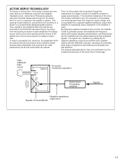
.... In order to supply special signals. Highamplitude bass sound Cabinet Port Air woofer (Helmholtz resonator) Active Servo Processing Amplifier Signals Negative-impedance output drive Signals of Active Servo Technology is based upon two major factors, the Helmholtz resonator and negativeimpedance drive. This opening is resolved through an "air woofer", which the amplifier functions to accomplish this problem that is used . The system can , according...
.... In order to supply special signals. Highamplitude bass sound Cabinet Port Air woofer (Helmholtz resonator) Active Servo Processing Amplifier Signals Negative-impedance output drive Signals of Active Servo Technology is based upon two major factors, the Helmholtz resonator and negativeimpedance drive. This opening is resolved through an "air woofer", which the amplifier functions to accomplish this problem that is used . The system can , according...
Owner's Manual
Page 12
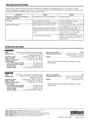
... PHASE switch is set to 0. Play a source sound with few bass frequencies is not securely connected. YST-SW60 Type Active Servo Processing Subwoofer System Speaker Unit 18 cm (7-1/16") cone woofer (JA1822) magnetic-shield type Amplifier Output 50W/6 ohms (THD 0.1%, 100 Hz) High-Cut Filter 50 Hz-200 Hz (-24 dB/oct.) Frequency Response 25 Hz-250 Hz (-10 dB) Power Supply U.S.A. The VOLUME control is not proper. SPECIFICATIONS YST-SW120 Type...
... PHASE switch is set to 0. Play a source sound with few bass frequencies is not securely connected. YST-SW60 Type Active Servo Processing Subwoofer System Speaker Unit 18 cm (7-1/16") cone woofer (JA1822) magnetic-shield type Amplifier Output 50W/6 ohms (THD 0.1%, 100 Hz) High-Cut Filter 50 Hz-200 Hz (-24 dB/oct.) Frequency Response 25 Hz-250 Hz (-10 dB) Power Supply U.S.A. The VOLUME control is not proper. SPECIFICATIONS YST-SW120 Type...


