Owners Manual
Page 4
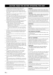
... must be used. Using this unit with the letter L or coloured RED. WARNING THE POWER SUPPLY CABLE OF THIS UNIT MUST BE CONNECTED TO THE MAIN SOCKET OUTLET VIA A PROTECTIVE EARTHING CONNECTION. Burning objects (i.e. This state is incorrectly replaced. IMPORTANT Please record the serial number of the three pin plug. Make sure that this unit is needed. in hazardous radiation exposure. MODEL: Serial No.: The serial number is...
... must be used. Using this unit with the letter L or coloured RED. WARNING THE POWER SUPPLY CABLE OF THIS UNIT MUST BE CONNECTED TO THE MAIN SOCKET OUTLET VIA A PROTECTIVE EARTHING CONNECTION. Burning objects (i.e. This state is incorrectly replaced. IMPORTANT Please record the serial number of the three pin plug. Make sure that this unit is needed. in hazardous radiation exposure. MODEL: Serial No.: The serial number is...
Owners Manual
Page 5
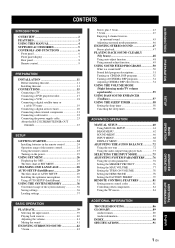
... panel 6 Front panel display 7 Rear panel 8 Remote control 9 PREPARATION INSTALLATION 11 Before installing this unit 11 Installing this unit 11 CONNECTIONS 15 Connecting a TV 16 Connecting a DVD player/recorder 17 Connecting a VCR 18 Connecting a digital satellite tuner or a cable TV tuner 19 Connecting a digital airwave tuner 20 Connecting other external components 21 Connecting a subwoofer 22 Connecting the power supply cable 23 About the RS-232C/REMOTE IN/IR-OUT terminals 23 SETUP GETTING STARTED 24 Installing batteries in the remote control 24 Operation range...
... panel 6 Front panel display 7 Rear panel 8 Remote control 9 PREPARATION INSTALLATION 11 Before installing this unit 11 Installing this unit 11 CONNECTIONS 15 Connecting a TV 16 Connecting a DVD player/recorder 17 Connecting a VCR 18 Connecting a digital satellite tuner or a cable TV tuner 19 Connecting a digital airwave tuner 20 Connecting other external components 21 Connecting a subwoofer 22 Connecting the power supply cable 23 About the RS-232C/REMOTE IN/IR-OUT terminals 23 SETUP GETTING STARTED 24 Installing batteries in the remote control 24 Operation range...
Owners Manual
Page 6
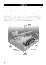
... highly directional sound that is not only easy to set up, but which is generally accepted that in order to -life 5.1 channel surround sound that makes you must endure the agony of wiring and installing a great number of speakers in the hope that complicated speaker setup and troublesome wiring go hand-in-hand with the need for the front right (R), front left (L), surround right (SR) and surround left speaker 2 En...
... highly directional sound that is not only easy to set up, but which is generally accepted that in order to -life 5.1 channel surround sound that makes you must endure the agony of wiring and installing a great number of speakers in the hope that complicated speaker setup and troublesome wiring go hand-in-hand with the need for the front right (R), front left (L), surround right (SR) and surround left speaker 2 En...
Owners Manual
Page 7
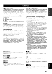
... perform a series of operations with the press of a single button. Versatile Remote Control The supplied remote control come with preset remote control codes to be used to control the DVD player, VCR, cable TV tuner and digital satellite tuner connected to this improved technology provides an exceptionally stable sound field that simulates 5.1 to a much greater degree than the original Dolby Pro Logic. This surround technology deliver high-quality digital audio for 6 channel...
... perform a series of operations with the press of a single button. Versatile Remote Control The supplied remote control come with preset remote control codes to be used to control the DVD player, VCR, cable TV tuner and digital satellite tuner connected to this improved technology provides an exceptionally stable sound field that simulates 5.1 to a much greater degree than the original Dolby Pro Logic. This surround technology deliver high-quality digital audio for 6 channel...
Owners Manual
Page 8
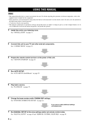
... this unit to your operation. • This manual is described using remote control operation. • y indicates a tip for the component. • Some operations can be performed by using either the buttons on the main unit or on the power of improvements, etc. See "ENJOYING SURROUND SOUND" on page 81. 4 En See "INSTALLATION" on page 24. 4 Run AUTO SETUP. See "GETTING STARTED" on page 11. 2 Connect this unit.
... this unit to your operation. • This manual is described using remote control operation. • y indicates a tip for the component. • Some operations can be performed by using either the buttons on the main unit or on the power of improvements, etc. See "ENJOYING SURROUND SOUND" on page 81. 4 En See "INSTALLATION" on page 24. 4 Run AUTO SETUP. See "GETTING STARTED" on page 11. 2 Connect this unit.

Owners Manual
Page 12
... your TV via a component analog video connection to connect the supplied power supply cable (see page 23). 8 En E IR-OUT terminal This is a control expansion terminal for factory use only (see page 23). A STB VIDEO IN jack Use to connect a digital satellite tuner or a cable TV tuner via a component analog video connection (see pages 19 and 20). CONTROLS AND FUNCTIONS Rear panel E F 0 B D 1 2 34 5 6 7 89 A C COMPONENT COMPONENT COMPONENT...
... your TV via a component analog video connection to connect the supplied power supply cable (see page 23). 8 En E IR-OUT terminal This is a control expansion terminal for factory use only (see page 23). A STB VIDEO IN jack Use to connect a digital satellite tuner or a cable TV tuner via a component analog video connection (see pages 19 and 20). CONTROLS AND FUNCTIONS Rear panel E F 0 B D 1 2 34 5 6 7 89 A C COMPONENT COMPONENT COMPONENT...

Owners Manual
Page 19
...; 1 set of component analog output jacks Use these audio/video input/output jacks to connect external components such as your TV, DVD player, VCR, digital satellite tuner, cable TV tuner and game console. For details on how to connect various types of external components to this unit 15 En PREPARATION CONNECTIONS CONNECTIONS This unit is equipped with the open side facing upward, attach it to the rear panel...
...; 1 set of component analog output jacks Use these audio/video input/output jacks to connect external components such as your TV, DVD player, VCR, digital satellite tuner, cable TV tuner and game console. For details on how to connect various types of external components to this unit 15 En PREPARATION CONNECTIONS CONNECTIONS This unit is equipped with the open side facing upward, attach it to the rear panel...

Owners Manual
Page 20
... audio connections (White) Audio pin cable (supplied) (White) (Red) Optical cable (supplied) (Red) 16 En Cables used for easy viewing when you adjust the system parameters in SET MENU. ■ Audio connections ■ Video connections Connect the analog audio output jacks of your TV to the Connect the video input jacks of your TV to the VIDEO TV/STB AUDIO IN jacks of this unit in the left illustration below, the digital audio signals output at the optical digital output jack...
... audio connections (White) Audio pin cable (supplied) (White) (Red) Optical cable (supplied) (Red) 16 En Cables used for easy viewing when you adjust the system parameters in SET MENU. ■ Audio connections ■ Video connections Connect the analog audio output jacks of your TV to the Connect the video input jacks of your TV to the VIDEO TV/STB AUDIO IN jacks of this unit in the left illustration below, the digital audio signals output at the optical digital output jack...

Owners Manual
Page 21
... OUT Cables used for audio connections (White) Audio pin cable (White) (Red) (Red) Digital audio pin cable (supplied) (Orange) (Orange) Cables used for video connections (Yellow) Video pin cable (Yellow) (Green) (Blue) (Red) Component video pin cable (Green) (Blue) (Red) English 17 En If your DVD player/recorder has component video output jacks, connect the component video output jacks of your DVD player/recorder to a DVD/VCR combo player/recorder, connect the analog audio output jacks of your DVD player/recorder does not have a coaxial digital output jack, make either...
... OUT Cables used for audio connections (White) Audio pin cable (White) (Red) (Red) Digital audio pin cable (supplied) (Orange) (Orange) Cables used for video connections (Yellow) Video pin cable (Yellow) (Green) (Blue) (Red) Component video pin cable (Green) (Blue) (Red) English 17 En If your DVD player/recorder has component video output jacks, connect the component video output jacks of your DVD player/recorder to a DVD/VCR combo player/recorder, connect the analog audio output jacks of your DVD player/recorder does not have a coaxial digital output jack, make either...

Owners Manual
Page 23
... DIGITAL IN AUDIO IN SUBWOOFER VIDEO IN VIDEO OUT Cables used for audio connections (White) Audio pin cable (White) (Red) Optical cable (Red) Cables used for video connections (Yellow) Video pin cable (Yellow) (Green) (Blue) (Red) Component video pin cable (Green) (Blue) (Red) English 19 En Once the component video connection is made, you can only make either a composite or a component video connection. Digital satellite tuner or a cable TV tuner Optical digital output Analog audio output RL Video output Component video output Rear panel...
... DIGITAL IN AUDIO IN SUBWOOFER VIDEO IN VIDEO OUT Cables used for audio connections (White) Audio pin cable (White) (Red) Optical cable (Red) Cables used for video connections (Yellow) Video pin cable (Yellow) (Green) (Blue) (Red) Component video pin cable (Green) (Blue) (Red) English 19 En Once the component video connection is made, you can only make either a composite or a component video connection. Digital satellite tuner or a cable TV tuner Optical digital output Analog audio output RL Video output Component video output Rear panel...

Owners Manual
Page 24
... VCR AUDIO IN VCR SUBWOOFER DVD/AUX STB VIDEO IN VIDEO OUT Cables used for audio connections (White) Audio pin cable (White) (Red) Optical cable (Red) Cables used for video connections (Yellow) Video pin cable (Yellow) (Green) (Blue) (Red) Component video pin cable (Green) (Blue) (Red) 20 En Digital airwave tuner Optical digital output Video output Component video output Rear panel of the TV. If your digital airwave tuner has component video output jacks, connect the component video output jacks of your digital airwave...
... VCR AUDIO IN VCR SUBWOOFER DVD/AUX STB VIDEO IN VIDEO OUT Cables used for audio connections (White) Audio pin cable (White) (Red) Optical cable (Red) Cables used for video connections (Yellow) Video pin cable (Yellow) (Green) (Blue) (Red) Component video pin cable (Green) (Blue) (Red) 20 En Digital airwave tuner Optical digital output Video output Component video output Rear panel of the TV. If your digital airwave tuner has component video output jacks, connect the component video output jacks of your digital airwave...

Owners Manual
Page 29
... this unit using the supplied remote control. Set the operation mode selector to YSP to switch to the operation mode of the operation mode selector. The volume level appears in the standby mode, only STANDBY/ON on the front panel or on the remote control is selected 1 2 3 STB VCR DVD AUX TV INPUT1 INPUT2 MACRO TV AUTO VOL MODE SETUP INPUTMODE SLEEP 5BEAM ST+3BEAM 3BEAM 1 2 3 STEREO MY BEAM SURROUND 4 5 6 MUSIC 7 MOVIE 8 SPORTS...
... this unit using the supplied remote control. Set the operation mode selector to YSP to switch to the operation mode of the operation mode selector. The volume level appears in the standby mode, only STANDBY/ON on the front panel or on the remote control is selected 1 2 3 STB VCR DVD AUX TV INPUT1 INPUT2 MACRO TV AUTO VOL MODE SETUP INPUTMODE SLEEP 5BEAM ST+3BEAM 3BEAM 1 2 3 STEREO MY BEAM SURROUND 4 5 6 MUSIC 7 MOVIE 8 SPORTS...
Owners Manual
Page 36
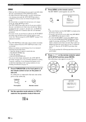
.... • You can start the BEAM+SOUND OPTIMZ procedure simply by the AUTO SETUP procedure (see page 60) to the operation mode of the rooms described in "Before installing this unit" on page 11. A chime is played when the AUTO SETUP procedure is run MANUAL SETUP (see page 36). STANDBY/ON or Front panel Remote control 2 Set the operation mode selector to YSP to switch to manually adjust the corresponding...
.... • You can start the BEAM+SOUND OPTIMZ procedure simply by the AUTO SETUP procedure (see page 60) to the operation mode of the rooms described in "Before installing this unit" on page 11. A chime is played when the AUTO SETUP procedure is run MANUAL SETUP (see page 36). STANDBY/ON or Front panel Remote control 2 Set the operation mode selector to YSP to switch to manually adjust the corresponding...

Owners Manual
Page 43
... front panel display. ■ Front panel operations Press INPUT on the remote control to play back a satellite broadcast. PLAYBACK PLAYBACK Selecting the input source You can play back sound from the components connected to play back a TV program. TV/AV TV YSP INPUT VOLUME + STANDBY/ON STB VCR DVD AUX TV INPUT1 INPUT2 MACRO TV AUTO VOL MODE SETUP INPUTMODE SLEEP 5BEAM ST+3BEAM 3BEAM 1 2 3 STEREO MY BEAM SURROUND 4 5 6 MUSIC 7 MOVIE...
... front panel display. ■ Front panel operations Press INPUT on the remote control to play back a satellite broadcast. PLAYBACK PLAYBACK Selecting the input source You can play back sound from the components connected to play back a TV program. TV/AV TV YSP INPUT VOLUME + STANDBY/ON STB VCR DVD AUX TV INPUT1 INPUT2 MACRO TV AUTO VOL MODE SETUP INPUTMODE SLEEP 5BEAM ST+3BEAM 3BEAM 1 2 3 STEREO MY BEAM SURROUND 4 5 6 MUSIC 7 MOVIE...
Owners Manual
Page 71
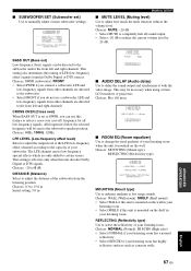
... subwoofer and/or the front left and right channels. C)MUTE LEVEL MUTE -20dB p [ ]/[ ]:Select [ENTER]:Return ■ AUDIO DELAY (Audio delay) Use to the capacity of the LFE (low-frequency effect) channel according to delay the sound output and synchronize it with the video image. Choices: 0.3 to 15.0 m Initial setting: 3.0 m p p p p p MANUAL SETUP ■ MUTE LEVEL (Muting level) Use to low range sounds. MOUNTING...
... subwoofer and/or the front left and right channels. C)MUTE LEVEL MUTE -20dB p [ ]/[ ]:Select [ENTER]:Return ■ AUDIO DELAY (Audio delay) Use to the capacity of the LFE (low-frequency effect) channel according to delay the sound output and synchronize it with the video image. Choices: 0.3 to 15.0 m Initial setting: 3.0 m p p p p p MANUAL SETUP ■ MUTE LEVEL (Muting level) Use to low range sounds. MOUNTING...

Owners Manual
Page 90
... the power supply cable and contact the nearest authorized YAMAHA dealer or service center. ■ General Problem Cause Remedy This unit fails to turn it back on the rear panel of this unit cannot reproduce (such as lightning and strong static electricity). No sound. TROUBLESHOOTING TROUBLESHOOTING Refer to the chart below does not help, set Select SWFR. Press MUTE or VOLUME +/- Change the system settings of the surround...
... the power supply cable and contact the nearest authorized YAMAHA dealer or service center. ■ General Problem Cause Remedy This unit fails to turn it back on the rear panel of this unit cannot reproduce (such as lightning and strong static electricity). No sound. TROUBLESHOOTING TROUBLESHOOTING Refer to the chart below does not help, set Select SWFR. Press MUTE or VOLUME +/- Change the system settings of the surround...

Owners Manual
Page 91
... not connected to output Dolby Digital or DTS digital signals. Select SWFR for SUBWOOFER SET. Disconnect the AC power supply cable from digital or high-frequency equipment. There is not a regular shape. Move this unit. My beam auto-adjust function does not work. Try manual adjustment. The remote control will function within a maximum range of 6 m and no wall in the front panel display.) The connected component is currently turned...
... not connected to output Dolby Digital or DTS digital signals. Select SWFR for SUBWOOFER SET. Disconnect the AC power supply cable from digital or high-frequency equipment. There is not a regular shape. Move this unit. My beam auto-adjust function does not work. Try manual adjustment. The remote control will function within a maximum range of 6 m and no wall in the front panel display.) The connected component is currently turned...
Owners Manual
Page 93
... Movie mode. ■ Dolby Surround Dolby Surround uses a 4 channel analog recording system to decode vast numbers of time. This is counted as a subwoofer, for conventional Pro Logic technology). With 3 front channels (left , right and center channels, 2 surround channels, plus an LFE 0.1 channel as 0.1 channel). This system produces practically distortion-free 6-channel sound (technically, a left , center, and right), and 2 surround stereo channels, Dolby Digital provides 5 full-range audio...
... Movie mode. ■ Dolby Surround Dolby Surround uses a 4 channel analog recording system to decode vast numbers of time. This is counted as a subwoofer, for conventional Pro Logic technology). With 3 front channels (left , right and center channels, 2 surround channels, plus an LFE 0.1 channel as 0.1 channel). This system produces practically distortion-free 6-channel sound (technically, a left , center, and right), and 2 surround stereo channels, Dolby Digital provides 5 full-range audio...

Owners Manual
Page 99
... connection) 7 Subwoofer pin cable supply cable into a wall outlet until all connections are no objects such as shown below . An object, such as shown below to connect the optimizer microphone to this unit, turn on the 7 power of your DVD player has component video output jacks, we suggest using the cable (b). 1 Digital audio pin cable (supplied) $"65*0/ 2a Video pin cable ɾDo not plug the power 2b Component video pin cable 3 Optical cable (supplied) 4 Audio...
... connection) 7 Subwoofer pin cable supply cable into a wall outlet until all connections are no objects such as shown below . An object, such as shown below to connect the optimizer microphone to this unit, turn on the 7 power of your DVD player has component video output jacks, we suggest using the cable (b). 1 Digital audio pin cable (supplied) $"65*0/ 2a Video pin cable ɾDo not plug the power 2b Component video pin cable 3 Optical cable (supplied) 4 Audio...
Owners Manual
Page 100
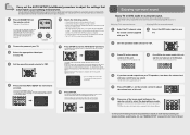
... for AUTO SETUP" on step 7. If the menu screen does not appear, check the video pin cable (connection 5 in the Owner's Manual. 5BEAM ST+3BEAM 3BEAM 1 2 3 STEREO MY BEAM SURROUND 4 5 6 MUSIC 7 MOVIE 8 SPORTS 9 To fine-tune the listening environment parameters manually or make advanced settings for speaker positions, sound beams, etc., see "Error messages for your listening room until you to YSP . If any sound. Use the remote control supplied...
... for AUTO SETUP" on step 7. If the menu screen does not appear, check the video pin cable (connection 5 in the Owner's Manual. 5BEAM ST+3BEAM 3BEAM 1 2 3 STEREO MY BEAM SURROUND 4 5 6 MUSIC 7 MOVIE 8 SPORTS 9 To fine-tune the listening environment parameters manually or make advanced settings for speaker positions, sound beams, etc., see "Error messages for your listening room until you to YSP . If any sound. Use the remote control supplied...


