Owners Manual
Page 5
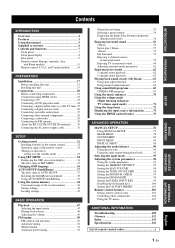
... the front panel keys 100 Setting the FACTORY PRESET 101 Remote control features 103 Setting remote control codes 103 Controlling other external components 28 Connecting a subwoofer 29 Connecting the FM antenna 30 About the RS-232C/IR-OUT/IR IN terminals ........ 30 Connecting the AC power supply cable 31 SETUP Getting...
... the front panel keys 100 Setting the FACTORY PRESET 101 Remote control features 103 Setting remote control codes 103 Controlling other external components 28 Connecting a subwoofer 29 Connecting the FM antenna 30 About the RS-232C/IR-OUT/IR IN terminals ........ 30 Connecting the AC power supply cable 31 SETUP Getting...

Owners Manual
Page 7
... unit employs decoders compatible with preset remote control codes used on various digital media such as the YDS-10, sold separately by Yamaha Electronics Corp. This surround technology delivers high-quality digital audio for up to 5.1 discrete channels to produce a directional and more realistic...in a noisy environment. In addition, the remote control is a redesigned version of Dolby Pro Logic that employs 2 stereo surround channels, a subwoofer, and a greatly enhanced steering logic. Music mode and Cinema mode are available to play back the XM HD content of XM Satellite Radio...
... unit employs decoders compatible with preset remote control codes used on various digital media such as the YDS-10, sold separately by Yamaha Electronics Corp. This surround technology delivers high-quality digital audio for up to 5.1 discrete channels to produce a directional and more realistic...in a noisy environment. In addition, the remote control is a redesigned version of Dolby Pro Logic that employs 2 stereo surround channels, a subwoofer, and a greatly enhanced steering logic. Music mode and Cinema mode are available to play back the XM HD content of XM Satellite Radio...

Owners Manual
Page 13
... DIGITAL IN jack Connect an external component via an analog connection (see page 24). 0 DOCK terminal (U.S.A., Canada, and Australia models only) Connect the Yamaha iPod universal dock (such as a TV or a projector connected to this unit (see page 22). 4 AC IN Connect the supplied AC power supply...This is a control expansion terminal for commercial use only (see page 30). 6 ANTENNA jack Connect the FM antenna (see page 30). 7 SUBWOOFER jack Connect your subwoofer (see page 29). 8 TV/STB AUDIO IN jacks Connect your DVD player via a coaxial digital connection (see page 28). and Canada models...
... DIGITAL IN jack Connect an external component via an analog connection (see page 24). 0 DOCK terminal (U.S.A., Canada, and Australia models only) Connect the Yamaha iPod universal dock (such as a TV or a projector connected to this unit (see page 22). 4 AC IN Connect the supplied AC power supply...This is a control expansion terminal for commercial use only (see page 30). 6 ANTENNA jack Connect the FM antenna (see page 30). 7 SUBWOOFER jack Connect your subwoofer (see page 29). 8 TV/STB AUDIO IN jacks Connect your DVD player via a coaxial digital connection (see page 28). and Canada models...

Owners Manual
Page 14
... to the video input jack of your TV via a component analog video connection (see pages 24 and 28). and Canada models only) Use to connect a Yamaha subwoofer equipped with a SYSTEM CONNECTOR terminal to 26). J STB COMPONENT VIDEO IN jacks Connect a digital satellite tuner or a cable TV tuner via a component analog video connection...
... to the video input jack of your TV via a component analog video connection (see pages 24 and 28). and Canada models only) Use to connect a Yamaha subwoofer equipped with a SYSTEM CONNECTOR terminal to 26). J STB COMPONENT VIDEO IN jacks Connect a digital satellite tuner or a cable TV tuner via a component analog video connection...

Owners Manual
Page 24
... this unit. Audio connection Video connection TV This unit AUX 3 INTELLIBEAM MIC INPUT VOLUME + STANDBY/ON DVD player 20 En Subwoofer portable audio player Digital satellite tuner or cable TV tuner VCR or game console For details on how to connect various types of...8226; 1 universal dock terminal (U.S.A., Canada, and Australia models only) For audio/video input • 2 HDMI input jacks For audio output • 1 subwoofer output jack For audio/video output • 1 HDMI output jack For video output • 1 composite video output jack • 1 set of component video...
... this unit. Audio connection Video connection TV This unit AUX 3 INTELLIBEAM MIC INPUT VOLUME + STANDBY/ON DVD player 20 En Subwoofer portable audio player Digital satellite tuner or cable TV tuner VCR or game console For details on how to connect various types of...8226; 1 universal dock terminal (U.S.A., Canada, and Australia models only) For audio/video input • 2 HDMI input jacks For audio output • 1 subwoofer output jack For audio/video output • 1 HDMI output jack For video output • 1 composite video output jack • 1 set of component video...

Owners Manual
Page 25
... cable clamp. y • We recommend that you are assigned to 96 kHz/24 bit) Dolby Digital, DTS, PCM (Orange) (Orange) 3.5 mm stereo mini plug cable 5 Subwoofer pin cable Video OSD video pin cable (supplied) / Video pin cable (Yellow) (Yellow) Component video pin cable (Green) (Blue) (Red) (Green) (Blue) (Red) ■ Notes...
... cable clamp. y • We recommend that you are assigned to 96 kHz/24 bit) Dolby Digital, DTS, PCM (Orange) (Orange) 3.5 mm stereo mini plug cable 5 Subwoofer pin cable Video OSD video pin cable (supplied) / Video pin cable (Yellow) (Yellow) Component video pin cable (Green) (Blue) (Red) (Green) (Blue) (Red) ■ Notes...

Owners Manual
Page 28
... TV Video Video pin cable Component video pin cable DVD player/recorder Audio Audio pin cable Digital audio pin cable 24 En COMPONENT ANTENNA COMPONENT SUBWOOFER STB DVD/AUX 2 VIDEO IN AUX 1 TV/STB AUX 1 AUDIO IN Rear panel of this unit. Notes • Check that your DVD player/recorder to...
... TV Video Video pin cable Component video pin cable DVD player/recorder Audio Audio pin cable Digital audio pin cable 24 En COMPONENT ANTENNA COMPONENT SUBWOOFER STB DVD/AUX 2 VIDEO IN AUX 1 TV/STB AUX 1 AUDIO IN Rear panel of this unit. Notes • Check that your DVD player/recorder to...

Owners Manual
Page 29
... prevent the optical cable from being unplugged, affix the optical cable in digital satellite tuner, cable TV tuner, or digital airwave tuner. ANTENNA COMPONENT COMPONENT SUBWOOFER STB DVD/AUX 2 VIDEO IN AUX 1 TV/STB AUX 1 AUDIO IN Rear panel of this unit DVD AUX 2 COAXIAL OPTICAL TV/STB AUX 1 DIGITAL IN...
... prevent the optical cable from being unplugged, affix the optical cable in digital satellite tuner, cable TV tuner, or digital airwave tuner. ANTENNA COMPONENT COMPONENT SUBWOOFER STB DVD/AUX 2 VIDEO IN AUX 1 TV/STB AUX 1 AUDIO IN Rear panel of this unit DVD AUX 2 COAXIAL OPTICAL TV/STB AUX 1 DIGITAL IN...

Owners Manual
Page 30
... of this unit. If your digital airwave tuner has component video output jacks, connect the component video output jacks of this unit. ANTENNA COMPONENT COMPONENT SUBWOOFER STB DVD/AUX 2 VIDEO IN AUX 1 TV/STB AUX 1 AUDIO IN Rear panel of this unit to the analog audio output jacks on your digital...
... of this unit. If your digital airwave tuner has component video output jacks, connect the component video output jacks of this unit. ANTENNA COMPONENT COMPONENT SUBWOOFER STB DVD/AUX 2 VIDEO IN AUX 1 TV/STB AUX 1 AUDIO IN Rear panel of this unit to the analog audio output jacks on your digital...

Owners Manual
Page 32
... DIGITAL IN or AUX 2 COAXIAL DIGITAL IN jack take priority over the analog audio signals input at the AUX 1 AUDIO IN jacks. ANTENNA COMPONENT COMPONENT SUBWOOFER STB DVD/AUX 2 VIDEO IN AUX 1 TV/STB AUX 1 AUDIO IN Rear panel of your DVD player/recorder, etc. If your component to the DVD...
... DIGITAL IN or AUX 2 COAXIAL DIGITAL IN jack take priority over the analog audio signals input at the AUX 1 AUDIO IN jacks. ANTENNA COMPONENT COMPONENT SUBWOOFER STB DVD/AUX 2 VIDEO IN AUX 1 TV/STB AUX 1 AUDIO IN Rear panel of your DVD player/recorder, etc. If your component to the DVD...

Owners Manual
Page 33
... power mode of this unit (U.S.A. PREPARATION Connections Connecting a subwoofer Connect the monaural input jack on your subwoofer and then run AUTO SETUP (see page 37) or select SWFR for BASS OUT in SUBWOOFER SET (see page 82). COMPONENT Rear panel of this unit...connector input Audio 5 Subwoofer pin cable Subwoofer English 29 En and Canada models) FM75 UNBAL. To output sound from the connected subwoofer. This connection alone does not output sound from the connected subwoofer, turn on this unit. and Canada models). When connecting a Yamaha subwoofer equipped with a SYSTEM...
... power mode of this unit (U.S.A. PREPARATION Connections Connecting a subwoofer Connect the monaural input jack on your subwoofer and then run AUTO SETUP (see page 37) or select SWFR for BASS OUT in SUBWOOFER SET (see page 82). COMPONENT Rear panel of this unit...connector input Audio 5 Subwoofer pin cable Subwoofer English 29 En and Canada models) FM75 UNBAL. To output sound from the connected subwoofer. This connection alone does not output sound from the connected subwoofer, turn on this unit. and Canada models). When connecting a Yamaha subwoofer equipped with a SYSTEM...

Owners Manual
Page 34
Connections Connecting the FM antenna Connect the supplied FM antenna to the FM ANTENNA jack on this unit (U.S.A. Rear panel of this unit STB DVD/AUX 2 VIDEO IN AUX 1 About the RS-232C/IR-OUT/IR IN terminals The RS-232C, IR-OUT, and IR IN terminals do not support normal external component connections. FM indoor antenna (supplied) FM75 UNBAL. COMPONENT ANTENNA COMPONENT SUBWOOFER Rear panel of this unit. and Canada models) IR-OUT IR IN RS-232C IR-OUT IR IN terminal RS-232C terminal IR-OUT terminal 30 En They are control expansion terminals for commercial use only.
Connections Connecting the FM antenna Connect the supplied FM antenna to the FM ANTENNA jack on this unit (U.S.A. Rear panel of this unit STB DVD/AUX 2 VIDEO IN AUX 1 About the RS-232C/IR-OUT/IR IN terminals The RS-232C, IR-OUT, and IR IN terminals do not support normal external component connections. FM indoor antenna (supplied) FM75 UNBAL. COMPONENT ANTENNA COMPONENT SUBWOOFER Rear panel of this unit. and Canada models) IR-OUT IR IN RS-232C IR-OUT IR IN terminal RS-232C terminal IR-OUT terminal 30 En They are control expansion terminals for commercial use only.

Owners Manual
Page 41
... if SOUND OPTIMZ only is selected. *2 The sound optimization procedure is skipped if BEAM OPTIMZ only is selected. *3 The subwoofer checking procedure is skipped if BEAM OPTIMZ only is selected. *2 *3 Checking the subwoofer and optimizing the beam delay, frequency, and volume Sound optimization SETUP English 37 En Just as you would arrange...
... if SOUND OPTIMZ only is selected. *2 The sound optimization procedure is skipped if BEAM OPTIMZ only is selected. *3 The subwoofer checking procedure is skipped if BEAM OPTIMZ only is selected. *2 *3 Checking the subwoofer and optimizing the beam delay, frequency, and volume Sound optimization SETUP English 37 En Just as you would arrange...

Owners Manual
Page 42
... (6.0 ft) from the center height of the unit with the IntelliBeam microphone facing upward at your normal listening position. MIN MAX MIN MAX Subwoofer 1 Press STANDBY/ON to turn off the power of this unit produces in your listening room. AUX 3 INTELLIBEAM MIC INTELLIBEAM MIC IntelliBeam microphone ... the sound beam output levels using MANUAL SETUP (see page 76) once the AUTO SETUP procedure is completed. • If a subwoofer with adjustable volume and crossover/high-cut frequency controls is connected to affix the IntelliBeam microphone at the same height as doing so may...
... (6.0 ft) from the center height of the unit with the IntelliBeam microphone facing upward at your normal listening position. MIN MAX MIN MAX Subwoofer 1 Press STANDBY/ON to turn off the power of this unit produces in your listening room. AUX 3 INTELLIBEAM MIC INTELLIBEAM MIC IntelliBeam microphone ... the sound beam output levels using MANUAL SETUP (see page 76) once the AUTO SETUP procedure is completed. • If a subwoofer with adjustable volume and crossover/high-cut frequency controls is connected to affix the IntelliBeam microphone at the same height as doing so may...

Owners Manual
Page 44
... later depending on the varying conditions of your listening environment (see page 45). 1 Press STANDBY/ON to turn on the power of the subwoofer. Close the curtains. 4. A set of settings optimized according to the specific conditions of the rooms described in "Before installing this unit. ...ENTER ENTER ;AUTO SETUP . 1)BEAM+SOUND OPTIMZ 2)BEAM OPTIMZ only 3)SOUND OPTIMZ only [ ]/[ ]:Up/Down [ENTER]:Enter p p TV/AV YSP 40 En A chime is played when the AUTO SETUP procedure is displayed on the screen. The following operations in step 5 is run MANUAL SETUP (see...
... later depending on the varying conditions of your listening environment (see page 45). 1 Press STANDBY/ON to turn on the power of the subwoofer. Close the curtains. 4. A set of settings optimized according to the specific conditions of the rooms described in "Before installing this unit. ...ENTER ENTER ;AUTO SETUP . 1)BEAM+SOUND OPTIMZ 2)BEAM OPTIMZ only 3)SOUND OPTIMZ only [ ]/[ ]:Up/Down [ENTER]:Enter p p TV/AV YSP 40 En A chime is played when the AUTO SETUP procedure is displayed on the screen. The following operations in step 5 is run MANUAL SETUP (see...

Owners Manual
Page 46
...[ENTER] key to exit AUTO SETUP and then run the AUTO SETUP procedure again. • Depending on the environment of the subwoofer and run the procedure again from the YSP and the listening position. The following screen is displayed as a result. For details, see "Using the system memory" on page... APPLICABLE" is displayed even though a subwoofer is connected to the same value even if "5 BEAM" is displayed for AUTO SETUP" on page 43. AUTO SETUP COMPLETE Your YSP unit may be set to this case, see ERROR E-1 in step 8, the following screen is displayed, we recommend running the AUTO...
...[ENTER] key to exit AUTO SETUP and then run the AUTO SETUP procedure again. • Depending on the environment of the subwoofer and run the procedure again from the YSP and the listening position. The following screen is displayed as a result. For details, see "Using the system memory" on page... APPLICABLE" is displayed even though a subwoofer is connected to the same value even if "5 BEAM" is displayed for AUTO SETUP" on page 43. AUTO SETUP COMPLETE Your YSP unit may be set to this case, see ERROR E-1 in step 8, the following screen is displayed, we recommend running the AUTO...

Owners Manual
Page 67
In addition, no audio is output from the subwoofer connected to YSP. TV/AV YSP 2 Press and hold MY BEAM for more than two seconds. Make sure that the listening room is as quiet as the beam mode, the surround .... • The batteries in the remote control may occur if the listening room is noisy. DECODE 0 +10 ENHANCER ENTRY MENU CAT/ A-E DISPLAY ENTER TV/AV YSP RETURN (U.S.A. Using auto-adjust function The My Beam microphone on the remote control collects the test tones from this unit. and Canada models) Note If...
In addition, no audio is output from the subwoofer connected to YSP. TV/AV YSP 2 Press and hold MY BEAM for more than two seconds. Make sure that the listening room is as quiet as the beam mode, the surround .... • The batteries in the remote control may occur if the listening room is noisy. DECODE 0 +10 ENHANCER ENTRY MENU CAT/ A-E DISPLAY ENTER TV/AV YSP RETURN (U.S.A. Using auto-adjust function The My Beam microphone on the remote control collects the test tones from this unit. and Canada models) Note If...

Owners Manual
Page 80
...parameters in SOUND MENU and BEAM MENU are automatically set of settings optimized according to the audio and video input. Item TONE CONTROL SUBWOOFER SET MUTE LEVEL AUDIO DELAY ROOM EQ DD/DTS Dynamic Range TruBass Features Adjusts the output level of the listening room. Adjusts the...SET XM ANTENNA LEVEL (U.S.A. Selects the initial input of Dolby Digital or DTS signals. Page 88 89 89 76 En Adjusts the various subwoofer settings. Adjusts the dynamic range of the source. Item SETTING PARAMETERS BEAM ADJUSTMENT IMAGE LOCATION Features Adjusts the listening room and listening position ...
...parameters in SOUND MENU and BEAM MENU are automatically set of settings optimized according to the audio and video input. Item TONE CONTROL SUBWOOFER SET MUTE LEVEL AUDIO DELAY ROOM EQ DD/DTS Dynamic Range TruBass Features Adjusts the output level of the listening room. Adjusts the...SET XM ANTENNA LEVEL (U.S.A. Selects the initial input of Dolby Digital or DTS signals. Page 88 89 89 76 En Adjusts the various subwoofer settings. Adjusts the dynamic range of the source. Item SETTING PARAMETERS BEAM ADJUSTMENT IMAGE LOCATION Features Adjusts the listening room and listening position ...

Owners Manual
Page 86
... - + . p p p [ ]/[ ]:Up/Down [ ]/[ ]:Sel [ENTER]:Return TREBLE (Treble) Use to 95% Initial setting: 0% C)IMAGE LOCATION . B)SUBWOOFER SET . The higher the percentage, the louder the output from the center. BASS OUT;;;;;FRONT CROSS OVER;;;100Hz LFE LEVEL;;;;;;0dB DISTANCE;;;;;;3.0m p [ ]/[ ]:Up/Down...With the front right channel adjusted p p p SOUND MENU Use to manually adjust the various parameters related to the sound output. A)TONE CONTROL B)SUBWOOFER SET C)MUTE LEVEL D)AUDIO DELAY E)ROOM EQ F)DD/DTS Dynamic Range G)TruBass [ ]/[ ]:Up/Down [ENTER]:Enter p p ■ ...
... - + . p p p [ ]/[ ]:Up/Down [ ]/[ ]:Sel [ENTER]:Return TREBLE (Treble) Use to 95% Initial setting: 0% C)IMAGE LOCATION . B)SUBWOOFER SET . The higher the percentage, the louder the output from the center. BASS OUT;;;;;FRONT CROSS OVER;;;100Hz LFE LEVEL;;;;;;0dB DISTANCE;;;;;;3.0m p [ ]/[ ]:Up/Down...With the front right channel adjusted p p p SOUND MENU Use to manually adjust the various parameters related to the sound output. A)TONE CONTROL B)SUBWOOFER SET C)MUTE LEVEL D)AUDIO DELAY E)ROOM EQ F)DD/DTS Dynamic Range G)TruBass [ ]/[ ]:Up/Down [ENTER]:Enter p p ■ ...

Owners Manual
Page 87
...: NORMAL (Normal), HI ECHO (High echo) • Select NORMAL if your listening room has a normal reflectivity. • Select HI ECHO if your subwoofer. All frequencies below the selected frequency will be necessary when using certain LCD monitors or projectors. p p C)MUTE LEVEL MUTE -20dB p [ ]/[ ]:Select... is set to completely halt all lowfrequency signals. Choices: MUTE, -20 dB • Select MUTE to SWFR, you connect a subwoofer. Choices: MOUNTING (Mount type), REFLECTING (Reflectivity type) E)ROOM EQ . REFLECTING (Reflectivity type) Use to delay the sound output and...
...: NORMAL (Normal), HI ECHO (High echo) • Select NORMAL if your listening room has a normal reflectivity. • Select HI ECHO if your subwoofer. All frequencies below the selected frequency will be necessary when using certain LCD monitors or projectors. p p C)MUTE LEVEL MUTE -20dB p [ ]/[ ]:Select... is set to completely halt all lowfrequency signals. Choices: MUTE, -20 dB • Select MUTE to SWFR, you connect a subwoofer. Choices: MOUNTING (Mount type), REFLECTING (Reflectivity type) E)ROOM EQ . REFLECTING (Reflectivity type) Use to delay the sound output and...

